
Service Manual


brake plate hub and lever and remove the brake
plate assembly. The brake pad is not replaceable
separately. Instead, use a complete brake plate
assembly.
10.
If
necessary, remove the flanged head capscrew
securing the brake lever and hub to the housing.
CAUTION! The brake plate lever
is
under some
spring loading. Heavy gloves and eye
protection are recommended when removlng
the brake plate lever.
NOTE: Do not use an air wrench on
the
brake
lever self-tapping screw as thread damage to the
housing may result.
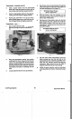
11. Remove the brake plate and hub assembly from
the housing and disassemble the seal,
or
oil
impregnated bushing, the hub, self-tapping
capscrew and washer from the brake lever. Be
careful not to lose the plastic bushing which fits
on the end of the brake spring rod. See Figure
94.
Figure 94
12. Complete disassembly of the brake plate by
removing the brake plate screws and the bearing
block.
13. Remove the
two
bearings from the bearing block
by pressing the bearings out on an arbor press.
Press only on the outer race to prevent bearing
damage (use an appropriately sized arbor or a
28 mm (1-1/8'”) socket.
14. inspect all
parts
for damage and/or wear and
replace as necessary.
BBC
Under Deck Components Assembly
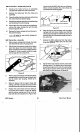
1. Check
to
make sure that the brake plate seal
is
in
good condition, then stretch onto the brake
plate bushing. See Figure 95.
Vacu-Power Mower
55
BRAKE
PLATE
BUSHING
BUSHING
Figure 95
Hook the control link
in
the slot on the brake lever.
Place the spring and the bushing onto the brake
rod then slip
the
bushing and brake rod through
the hole provided
in
the brake lever. Finally, install
the bushing hub and flanged head self-tapping
screw with washer through the brake lever.
Brake Plate Capscrew Torque:
25.5 N-m (225
in
Ibs)
NOTE:
If
the self-tapping screw strips the threads
in
the housing, do not helicoil, rather, place a
hexnut
in
the recess provided
in
the top side of
the deck.
Loosely secure the brake plate, complete with
brake pad to the brake lever and brake hub
as
shown
in
Figure 96. Note that the carriage bolt
should go through the brake plate first. Secure
with a nylon locknut
but
do not tighten
at
this
time. This will allow proper alignment
of
the idler
pulley later.
Install an
idler
hub
into
each side of the
idler
pulley bearing, then slip the belt onto the idler
pulley. Slip the entire assembly between the
brake plate
and
brake lever. Secure with the
carriage bolt and nylon locknut as shown
in
Figure 96.
Tighten both idler pulley carriage bolts. Make
sure that the idler pulley spins freely.
Idler Pulley Bolt Torque:
11.33 N-m
(100
in
Ibs)
Install the BBC flywheel onto the crankshaft,
making certain that the slots
in
the BBC flywheel
align with the tabs on the bottom
of
the
self-propel pulley.
BBC System