
Service Manual


Transmission Operation (cont’d)
with a roll
pin
so
the gear sleeve always rotates with
the output shaft. The gearselection system determines
which one of these three gears will be coupled with the
gear sleeve
and
the output shaft. This determines the
final drive ratio. For more information on final speeds
at various throttle settings, see Figure 61.
Figure
60
Gear
selection
System: Gear selection is determined
by moving sliding shift keys
in
a sleeve that
is
FIXED to
the output shaft. These keys engage one of the three
gears that rotate on the gear sleeve. Once the key
engages one of the gears, that GEAR will rotate
at
the
same speed
as
the output shaft. This determines the
final drive ratio, shown
in
Figure 61.
Ground Speed Ground Speed
Gear @3000RPM @2000RPM
I
1
1.8 mph
2.5
rnph
3.8 mph
3
1.8
mph
2.7 mph
2
1.2 mph
Figure 61
The
shift
keys are trapped on one end by the shift
collar. Movement
of
the shift fork positions the shift
collar and shift key. The shift fork is supported, both
top and bottom, by nylon bushings for smooth
operation and long wear. See Figure 62.
The operator controls movement
of
the shift fork by
means of the gear selection control and cable. For
more information on this,
see
Gear Selection Control,
page
34.
NOTE: There are no detents
in
or on the transmission
on 1988 and 1989 Vacu-Power mowers.
General
Information:
The
upper gear case half
is
cast
-aluminum. The lower transmission cover
is
made of
stamped steel
and
the gears are powdered metal.
Figure
62
Output shaft and intermediate shaft construction is of
steel and both are supported by
oil
impregnated
powdered metal bushings.
Lubrication is provided by 177 cc (6
oz)
of
No.
2
lithium-
based grease.
Transmission Removal
Complete transmission removal on the Vacu-Power
mower
is
quite easy and
is
recommended for most
self-propel system repairs.
1.
Remove the spark plug lead from the engine to
prevent accidental starting.
2.
Place the ground speed selector
in
neutral. This
will make
it
easier to remove the speed selection
cable later.
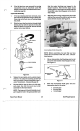
3.
Remove the two flanged head self-tapping
screws securing the screen panel to the housing
and
remove the panel. See Figure
63.
4.
Remove the black plastic transmission cover
from the top rear
of
the housing.
5.
Remove the
two
flanged head self-tapping
screws securing the
belt
cover to the top of the
transmission.
Pull
the cable from
belt
guide and
remove the
belt
guide.
Vacu-Power Mower
n