
Service Manual


9.
Remove the
two
nylon locknuts securing the right
hand BBC cover to the BBC control box
and
remove the right hand control box half.
IO.
Carefully pull the traction control cable from the
traction control lever in the BBC control box and
remove the cable. Remove the cable tie securing
the
cables to the handle only
if
necessary.
Traction Control Cable Installation
1.
Slip the new traction control cable into the
traction lever inside the BBC control box
if
so
equipped.
2.
Make sure that all BBC
or
zone start components
are still
in
place (consult Handle Assembly
section, page
67,
if
necessary) then install the
right-hand BBC case half and secure
with
the
flanged and the regular nylon locknuts.
NOTE:
The flanged nylon locknut fits on the rear
carriage
bolt.
secure the BBC case halves.
3.
Install the three flanged head screws to fully
4.
Bend the control panel tab forward slightly to
provide complete engagement with the control
when put
in
place. Snap the throttle control
in
place.
5.
Route the traction control cable through the
existing tie strap
(or
if
necessary, install a new
one) being sure that the tie strap does not kink
or
damage any cables.
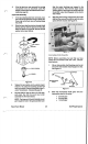
6.
Route the traction control cable on the outside
of
the handle and handle latch and down to the
transmission bet guide. Insert the end of the
cable into the belt guide
as
shown in Figure
50.
Figure
50
7.
Pull the cable tight, causing the transmission to
rock back, then insert the end of the sheath into
the cable support bracket from the top.
Vacu-Power Mower
37
8.
Line up the black plastic transmission cover with
the guides on the deck
and
the cable support
bracket and slide into place.
NOTE:
It
may
be
necessary to reach under the
deck and
tilt
the transmission back slightly to get
it
to drop into place.
9.
Install the screen panel by slipping the traction
cable
and
the BBC cable,
if
so
equipped, into the
slot
provided. Make sure
that
the top
of
the
screen panel slips below the lip
at
the top of the
housing. Secure with the
two
self-tapping
flanged head capscrews.
IO.
Check adjustment of the traction control cable
and adjust
if
necessary
as
described below.
Traction Control Cable Adjustment
The traction control cable is properly adjusted when all
slack
is
removed from the cable
and
the control bar
is
at
3.8
cm (1-1/2”) from the handle. (You can tell when
all slack is removed from the traction cable by feeling
for slight resistance as the control bar is raised and
also by watching
for
slight movement of the black
traction cable sheath.)
Figure 51
1.
If
adjustment
is
required, loosen the
two
jam nuts
on the traction control cable. (If
in
doubt which
Self-Propel System