
Service Manual


Dethatcher Assembly (cont'd)
2.
Nest each tine loop between the embossed
'dimples' with bent tips facing forward toward
tab cutouts
'A'
and secure with one
5/16'
X
3/4”
carriage bolt,
a
special washer,
one
5/16'
lock
washer and a
5/16'
hex nut Tighten securely.
3.
Install both safety wires through the tine coils and
bend the ends over to secure (use pliers).
CAUTION! Failure to install safety wires can
result
in
personal injury if a tine. should
disengage from the tine tray.
4.
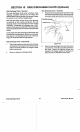
See Figure
135
to identify the type of front pivot
arms which mount the wheels to your mower.
Figure
135
Once you've identified the pivot arm used
on
your
mower, refer to the following table to determine which
stop bracket to use.
5.
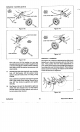
Turn the tine tray right side
up
and install the
frame bar, right hand mount bar, and left hand
mount bar to the inside
of
tabs
'A'
with offsets
76
it toward the center of the tray. See Figures
136
and
137.
OFFSETS TO INSIDE
Figure
136
OFFSET
A
Figure
137
6.
Insert one
5/16"
X
1”
carriage bolt, threads
FACING OUTWARD, through the FRONT square
hole
in
the
left
side of the frame bar, the FRONT
square hole
in
the left-hand bar and through the
round hole in the left-hand tab
'A'
on
the tine tray.
Secure with one
5/16'
lock washer and
a
5/16'
hex
nut.
7.
Follow the same procedure for the right side.
8.
Install a
5/16”X
1'
carriage bolt, threads FACING
OUTWARD, through the rear square hole
in
the
right-hand and the left-hand side of the frame bar
and secure with
two
5/16"
flat washers,
5/16'
lock
washers and
5/16'
hex nuts. Tighten these
fasteners securely.
9.
See Figure
138.
Assemble the wheel mount
bracket to the frame bar and one
5/16'
X
3/4”
carriage bolt inserted through the square hole
and secured with one
5/16'
lock washer, and one
5/16'
hex
nut
on the inside of the frame bar.
Tighten securely.
Vacu-Power Mower