
Service Manual


8.
If
the left pivot arm was removed for servicing,
reassemble now as described under Rear
Height-of-Cut System and Wheel Pinion Clutch
Assembly, page
40.
Input
Shaft
Assembly:
1.
If
the
input
bearing had been removed, press
a
new one into the gearcase using
an
arbor press.
Press only on the outer race
or
bearing damage
may result.
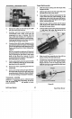
2. Slide the input shaft and pinion through the ball
bearing and top with the spacer and
two
pulley
halves
as
shown
in
Figure
69.
Secure
with
a flat
washer and a nylon locknut.
I
Figure
69
3.
Tighten the input pulley nut by using an impact
wrench
or
by using the cutaway gearcase half
and end wrench method described
in
step
3,
under Transmission Disassembly, page
43.
4.
Slip the shift fork into
the
slot on the shift collar
and place the shift fork and output shaft
assembly into
the
transmission.
NOTE:
The long end of
the
shift fork shaft should
go through the hole in the gearcase. Make sure
that the output bushings are trapped in the
proper
locations. Note
that
the larger output
bushing goes
on
the longer end
of
the shaft and
the shorter output bushing goes
on
the shorter
end
of
shaft.
5.
Slide the yoke bushing
onto
the lower end of the
shift
fork then secure the shift fork with the white
nylon
shift
fork retainer. See Figure
70.
SHIFT
FORK
RETAINERS
Figure
70
Intermediate
Shaft
Assembly:
NOTE: Before assembling, be sure that you have
coated the intermediate shaft with a No. 2 lithium
based grease.
1. Slip an intermediate shaft bushing
onto
the
left
end of the intermediate shaft, flanged end first.
See Figure
71.
INTERMEDIATE
SHAFT
GEARS
SPACERS
Figure
71
2. Slide the intermediate shaft gears onto the
intermediate shaft in this order:
25-tooth gear
20-tooth gear
15-tooth gear
Vacu-Power
Mower
45
Self-Propel
System