
Service Manual


SECTION
1
FRONT SUSPENSION
Front Suspension Operation
Since the introduction of this model
in
1988,
there have
been a number of different front suspension
configurations which have different parts used.
However, the basic design has remained the same.
The wheels rotate on a shoulder bolt. The wheel and
tire assembly is supported by oil impregnated
bushings which are permanently lubricated, although
occasional oiling will increase service life.
The wheel bolts are fastened to pivot arms. The pivot
arms pivot on a shoulder bolt to allow changes
in
height-of-cut. Height-of-cut is determined by the spring
arm detent that slips into various slots molded into the
housing. These slots are marked and allow adjustment
from
25
to
75
mm
in
13
mm increments
(1”
to
3'
in
l/2”
increments).
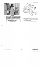
Front Suspension Disassembly
Four different front suspension configurations have
been used. See Figure
33.
Figure
33
1.
Remove the shoulder bolt securing the wheel to
the pivot arm. Remove the wheel and tire
assembly along with the shoulder bolt and the
nylon locknut.
2.
Remove the shoulder bolt securing the pivot arm
to the housing and remove the pivot and spring
arm assembly, complete with washers and
fasteners.
3.
Remove the spring arm from the pivot arm.
in
some cases
it
will be secured with a socket head
machine screw.
In
other cases, the spring arm
with be retained with detents.
NOTE:
If the pivot arm you are working on
resembles pivot arm
'B'
above,
it
can be further
disassembled by removing the steel plate.
However, these plates and pivot arm assemblies
are not available separately and have been
superceded by the system denoted by
'D'
in
Figure
35.
4.
The knob can be removed from the spring arm
by pressing on the detent through the hole
in
the
knob.
It
is not glued on.
Front Suspenslon Assembly
See Figures
34
and
35.
1.
Assemble the spring arm and knob
so
that the
detent on the spring arm falls
in
the hole on the
knob.
KNOB
PIVOT
ARM
SPRING
ARM
PIVOT
SCREW
I
WASHER
Front Suspension
30
Vacu-Power Mower