
Service Manual


SECTION
11
DETHATCHER
(Optional)
Dethatcher Safety Information
1.
Operate your dethatcher only when there is
adequate light.
2. Remove all debris such as wire, bottles, cans,
sticks, and stones from the area to be
dethatched.
3.
Always remove the spark plug wire and
disconnect the battery on electric start mowers
before servicing your mower dethatcher.
4.
Before each use, check to make sure all
fasteners are tight, tines are functioning properly,
and safety wires are
in
place.
5.
Reduce speed and cautiously dethatch any area
(rough ground) of the turf that may have hidden
hazards.
6.
Do
not leave your mower running while
unattended stop
the
engine and remove the
ignition key if
so
equipped.
7.
Make a visual check of the dethatcher stop
bracket
it
must be
in
the proper location and
tight!
8.
Store dethatcher on the floor to prevent any
injuries from occurring.
Dethatcher Operation
When dethatching, an overlap
or
cross-hatch pattern
is recommended. While all lawns are different, the ideal
amount of thatch
left
on the lawn would be about
3
mm
(1/8')
thick. Very dense lawns generally require more
frequent dethatching than do less dense lawns.
Grass should be less than 7.5 cm
(3")
tall for proper
tine action. The tines should deflect back and
then
independently 'flip' the thatch up and forward.
If
the
tines tend to drag, raise them a little and recheck the
'flipping' action. Adjust the tine tray up
or
down as
necessary for proper action.
Dethatcher Introduction
CAUTION! Carefully read and follow safety lnfor-
mation (Cautions)
in
this manual and the Operator's
Manual which came with your mower to prevent
injury
or
damage.
NOTE:
References to RIGHT
SIDE
and LEFT
SIDE
are
made while standing
in
the operator's position behind
the dethatcher (or the mower).
When correctly assembled and adjusted, and with
proper care, your dethatcher will provide years
of
trouble-free lawn maintenance.
Arrange each kind of hardware into a group to ease
assembly.
NOTE: Locknuts must be used where specified. They
have a slightly oblong hole
or
a fiber insert and are
domed on one end.
Tools
required for assembly:
-screwdriver (flat)
1
-pair of pliers (slip-joint recommended)
1-hammer
1-7/16” wrench
1-1/2* socket
1-9/16' socket
1-3/4”
socket
1
-socket wrench handle
1
-medium side adjustable wrench (optional)
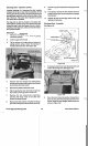
Dethatcher Assembly
1. Install the 6 tines to the tine tray by laying the tray
on a flat surface with the flanges facing up. See
Figure
134.
Figure
134
Vacu-Power Mower
75
Dethatcher