
Service Manual


49
GTS 200
Pistons, Rings, and Rods
Pistons,
Rings, and
Rods
Contents
Piston
and Connecting Rod
49
. . . . . . . . . . . . . . . . . . . . . . . . .
Remove Piston and Connecting Rod
49
. . . . . . . . . . . . . .
Remove Piston Rings
49
. . . . . . . . . . . . . . . . . . . . . . . . .
Check Piston Ring Groove W
ear 50
. . . . . . . . . . . . . . . .
Check Piston Ring End Gap
50
. . . . . . . . . . . . . . . . . . . .
Check Connecting Rod
50
. . . . . . . . . . . . . . . . . . . . . . . .
Check Piston Pin and Piston Pin Bore
50
. . . . . . . . . . . .
Assemble Piston and Connecting Rod
50
. . . . . . . . . . . .
Install Piston Rings On Piston
51
. . . . . . . . . . . . . . . . . . .
Compress Rings
51
. . . . . . . . . . . . . . . . . . . . . . . . . . . . . .
Install Connecting Rod and Piston
51
. . . . . . . . . . . . . . .
Specification T
ables 52
. . . . . . . . . . . . . . . . . . . . . . . . . . . . . . .
Piston
and Connecting Rod
Note:
Crankcase cover
or sump must be removed before
piston and rod can be removed, Crankshaft and Camshaft,
page 53.
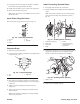
Remove Piston and Connecting Rod
1. Remove
connecting rod cap, Fig. 1
17.
1
Fig. 117 – Remove Piston and Connecting Rod
1. Box
wrench to remove screws
2. Remove
any carbon or ridge at top of cylinder bore to
prevent ring breakage.
3.
Push piston and rod out through top of cylinder
.
Note:
The GTS 200 engine uses oil drain slots in ring
lands, Fig. 1
18.
1
Fig. 118
– Oil Control Slots
1. Drain
slot
Remove Piston Rings
Remove
piston rings using Briggs & Stratton Tool #19340,
Piston Ring Expander
, Fig. 1
19.
1
Fig. 119
– Removing Rings
1. Piston
Note:
Some oil control rings consist of two thin steel rails and
a spring expander
. These steel rails cannot be removed with
Briggs & Stratton T
ool #19340, Piston Ring Expander
.
1.
Grasp one end of the steel rail and wind the rail from the
oil ring groove into the next ring groove.
2.
Repeat into the top ring groove and of
f the piston.