
Service Manual


42
GTS 200
Electric
Starter
3. A
dirty or worn armature commutator
.
4.
A shorted, open or grounded armature.
A.
Shorted armature (worn insulation, wires touching each
other) will be indicated by slow speed and high current
(amps).
B.
Open armature (broken wire) may not turn (no current
flow [amps]) or will have low RPM.
C.
Grounded armature (worn insulation, wire touching
armature) will not turn or may turn slowly and will
have excessive current (amps).
D. W
eak, loose, or cracked magnets.
5.
Armature end play, too much or none.
6.
Defective starter motor brake switch.
Check Brake Switch
1. Disconnect
interlock switch wires from spade terminals on
switch.
2.
Set meter to read
Ω
ohms. Zero meter
, if required.
3.
Connect meter test leads to two spade terminals of switch
(Fig. 95). Meter should read no continuity
.
Fig. 95
– Checking the Brake Switch
4. Push
switch lever in until switch clicks. Meter should read
low resistance.
Check Brake Switch Wiring
1. Disconnect
interlock switch wires from spade terminals on
switch and at starter motor connector
.
2.
Set meter to read
Ω
ohms. Zero meter
, if required.
3.
Connect one meter test lead to end of one wire inside
connector and other test lead to second connector terminal
for the same wire.
4.
Meter should read low or no resistance.
5.
Move wire inside connector
. Meter should not change
value.
6.
Replace or repair wiring if there is no continuity or
intermittent. Repeat for each wire in harness.
Disassemble Starter Motor
CAUTION
DO
NOT clamp motor housing in a vise or strike
with a steel hammer
. Starter motors contain two
ceramic magnets which can be br
oken or cracked
if motor housing is deformed or dented.
1.
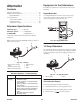
Study Fig. 96 prior to starter motor disassembly
.
17
16
15
14
13
12
11
9
8
7
6
5
4
3
2
1
10
Fig. 96
– Exploded V
iew
1. ’’E’’
retaining ring
2.
Starter gear helix
3.
Pinion gear
4.
Screws (3)
5. Cover
6. Gasket
7.
Felt washer
8.
Drive gear
9.
Pinion gear
10.
Drive end head bracket
11.
Thru bolts (2)
12. Housing
13.
Brush end cap (with
brushes, springs, and
connectors)
14.
End play washers
15. Armature
16. Commutator
17.
Thrust washers
2. Remove
“E” retaining ring and pinion gear
.