
Service Manual


Removing Gasoline from the Fuel Tank
1.
Stop the engine, allow it to cool and disconnect the
spark plug wire. Remove the key switch on electric
start models.
2.
Remove the cap from the fuel tank and use a pump
type siphon to transfer fuel into a clean gas can
or
container designed to hold gasoline. Note: this is the
only fuel removal procedure that should be used for
general maintenance.
Changing Crankcase Oil
Change the oil after the first
2
operating hours and after
every
25
hours. Since warm oil will drain better and carry
more contaminants than cold oil, run the engine for a
5
minute period before draining the oil.
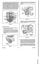
1.
Stop the engine, allow it to cool and disconnect the
spark plug wire. See Figure
4.
Figure
4
2.
Remove the' gasoline from the fuel tank: refer to
3.
Remove the dipstick from the oil
fill
tube and place a
4.
Tip the mower on its left side, allowing the oil to drain
"Removing Gasoline" on page
23.
drain pan next to the left side of the mower.
into the drain pan. See Figure
5.
Figure
5
5.
When the oil is drained, return the mower to its upright
position and add fresh oil to the engine. Refer to
"Filling the Crankcase with Oil" on pagexx. The crank-
case capacity is
25
oz
(.74
liters). When changing oil,
the crankcase may retain a small amount of oil, reduc-
ing the amount required to bring the oil level back to
normal.
Carburetor -Adjustment
1
.
Turn the idle mixture screw clockwise until
it
seats.
DO
NOT FORCE.
2.
Turn the idle mixture screw counterclockwise
1-1/2
turns. This will permit the engine to start and final
adjustment can be made with the engine running.
3.
Start the engine and allow
it
to warm up.
4.
While the engine is running, move the speed control
lever to the fast position until the hole "A"
in
the throttle
lever aligns with the hole
in
the throttle control bracket.
See Figure
6.
Use a
1/8"
(3
mm) diameter pin to hold
the holes
in
position.
ALIGNED
HOLES
'A'
Figure
6
5.
Adjust the high speed screw on the throttle control
bracket to obtain
3000,
100
RPM.
6.
Remove the pin and move the speed control lever to
the slow or idle position, until hole
“B”
in the throttle
control lever aligns with the hole
in
the throttle control
bracket.
Use
a
1/8"
(3
mm) diameter pin to hold the
holes in alignment.
7.
Adjust the idle speed stop screw to
1700,
100.
See
Figure
7.
16