
Service Manual


10.
Before installing the right control housing, check
to make sure that both cable sheath ends are
fully seated
in
their slots
in
the left housing. Also
make sure that the sleeve passes through all
components including the left control housing.
Finally, make sure that the roll
pin
passes
through the rocker arm and control bar.
Install the right control housing and secure
with
the
2
nylon locknuts.
11, Install the 3 flanged head screws that retain the
two
control box halves.
12. Check for proper operation of the entire BBC
system. Correct as required.
13. Bend the throttle control locking tab forward to
provide positive lock with the throttle control and
install the throttle control.
14.
Adjust the BBC cable as described under BBC
Adjusting the Blade Brake, page
26.
15.
Adjust the traction cable
if
you are working on a
self-propel model as described under Drive
Control Cable Adjustment, page 37.
BBC BELLCRANK
SYSTEM
BBC
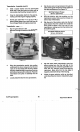
Bellcrank System Operation
The bellcrank system shown
in
Figure
86,
performs two
important functions. It changes the direction of control
input and also regulates the force applied to the blade
brake assembly.
Vacu-Power Mower
51
The directional change is accomplished by means of
a
bellcrank. The bellcrank rides on a nylon bushing and
is
attached to the cable support bracket.
Regulation
of
the force applied to the brake plate
assembly is accomplished by means of the
"over-tension' spring. The control link, which provides
the actual input to the brake plate assembly, is not
attached directly to the bellcrank,
but
rather through a
compression spring. This spring insures that the same
force is applied to the blade brake assembly each time
the blade is engaged. It also helps reduce shock loads.
Figure
86
NOTE:
This spring is
the
primary indicator
of
proper
BBC adjustment.
It
should measure 25.4k1.5 mm
(1
1/16")
with the blade engaged, when properly
adjusted.
If
spring measures more than
32
mm
(1-1/4"), correct by moving the jam nuts on the turn
buckle arrangement midway up the control cable.
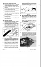
BBC Bellcrank System Disassembly
1.
Remove the flanged head self-tapping
capscrews securing the upper BBC cover to the
housing and remove the upper BBC cover.
2.
Pull the black plastic transmission cover up to
remove
it
from the housing. See Figure
87.
3.
Remove the shoulder bolt and flanged nut
securing the bellcrank to the control cable
bracket. Once loose, remove the bellcrank
assembly complete with control link and remove
from the unit. See Figure
88.
4.
Remove the bushing from inside the bellcrank.
BBC System