
Service Manual


SECTION
2
REAR SUSPENSION
(HP
Models
Only)
Hand Push Rear Suspension Operation
The rear suspension used
in
hand push versions of the
Vacu-Power mower serves two purposes: One,
it
supports the wheels, and two,
it
allows the height-
of-cut to be changed.
You will note many similarities between the hand push
system and the
self
propel system. This was intended
to maximize commonality between the machines.
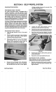
The wheel and tire assembly ride on shoulder bolts
that
are fastened into the pivot arms. See Figure
37.
Figure
37
Wheels and tires are not individually replaceable,
although they ride on oil impregnated bushings which
can be replaced. These bushings are permanently
lubricated. However, a few drops of oil at
50
hour
intervals will increase service life.
The pivot arms are supported by end caps. They are
retained inside the end caps by an axle that spans the
entire width of the deck.
A
washer and an E-clip keep
the pivot arms from coming
off
the end of the axle. This
arrangement allows the pivot arms to pivot.
Changing height-of-cut is accomplished by bending
the spring arm which is rigidly fastened to the pivot arm
by means of a socket head capscrew. Recesses
in
the
deck and a rivet
in
the center of the pivot arm provide
a means of retaining the desired height-of-cut. The
recesses provided allow the height-of- cut to
be
changed from
25
to
75
mm
in
13
mm increments
(1”
to
3”
in
l/2”
increments).
Hand Push Rear Suspension Disassembly
If rear suspension service is necessary,
it
will most
often be easiest to remove the whole assembly
and
then
perform the service.
Rear Suspension
32
1.
2.
3.
4.
5.
6.
7.
8.
Remove the spark plug wire to prevent acciden-
tal starting.
Drain the gasoline from the unit.
Remove the four flanged head capscrews
securing the end caps and safety shield to the
deck. Remove the safety shield assembly
and
the hand push rear suspension assembly.
Remove the shoulder bolt that secures the wheel
and
tire assembly to the pivot arm and remove
the wheel, washer
and
nylon locknut.
Remove the E-clips from each end of the axle.
Pull
the pivot arms, spring arm assembly and the
end caps from the axle.
Remove the spring arms from the pivot arms by
removing the socket head capscrews.
If required, the spring arm can be further
disassembled by removing the knob. Press on
the tab inside the hole
in
the knob and pull
off
vertically.
NOTE:
The spring arm uses a rivet to retain
it
in
a desired height-of-cut. These rivets are not
replaceable separately.
Inspect all parts for wear and/or damage and
replace as necessary.
Hand Push Rear Suspension Assembly
1.
If necessary, reassemble the spring arms by
installing a knob on top of the spring arm. Make
sure that the tab on the top of the spring arm rises
at least
1.5
mm
(.060”)
above the spring arm.
install the knob
so
that the concave part of the
knob and the concave part of the rivet are on
opposite sides. See Figure
38.
2.
Secure the spring arm to the
pivot
arm with a
socket head capscrew.
3.
Slide an end cap onto each end of the axle
as
shown
in
Figure
37.
Slide the spring arm
and
pivot arm assembly onto each side of the axle,
spring arm first.
Slide a flat washer onto each end of the output
shaft then secure the assembly with an E-clip on
each end.
n
4.
Install the assembly into the mower housing
using only the
two
front flanged head capscrews.
Vacu-Power Mower