
Installation Instructions


InstallingtheTiltCylinder
Tiltcylinderweight:11.3kg(25lb)
Note:Theretractedlengthofthetiltcylinderis51.4cm
(20.25inch)andtheroddiameteris44.5mm(1.75inch).
1.Aligntheholeinthemountingttingatthexedend
oftheliftcylinder—retractedlength51.4cm(20.25
inch);roddiameter44.5mm1.75inch)withthehole
mountinglugatthelift-armassemblyasshowninA
ofFigure38.
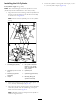
Figure38
1.Hairpin5.Hydraulicports
2.Mountinglug(lift-arm
assembly)
6.Rodtting(tiltcylinder)
3.Mountingtting(lift
cylinder—xedend)
7.Mountinglug(backll
blade)
4.Clevispin(1-1/4x4-7/16
inch)
2.Securethemountingttingoftheliftcylindertothe
mountinglugwithaclevispin(1-1/4x4-7/16inch)
andhairpin(Figure38).
3.Aligntheholesintherodttingofthetiltcylinder
withthecylinderlugofthebackllbladeasshownin
BofFigure38.
Note:Manuallyextendorcollapsetheliftcylinderas
neededtoaligntheholes.
4.Securetherodttingtothecylinderlugwithaclevis
pin(1-1/4x4-7/16inch)andahairpin(Figure38).
5.Liftthebackllbladeslightlywiththeliftingequipment,
removethejackstands,lowerthebackllblade,and
removetheliftingequipment.
8
InstallingtheHydraulicHoses
Partsneededforthisprocedure:
1
Liftcylinderextendhose(3/8x23inches)
1
Liftcylinderretracthose(3/8x31-1/4inch)
1
Tiltcylinderextendhose(3/8x49-1/4inch)
1
Tiltcylinderretracthose(3/8x62-1/4inch)
4
Clampblock(2-hose)
2
Bolt(3/8x1-3/4inch)
2
Washer(3/8inch)
2
Coverplate
1
Cabletie
InstallingtheLiftCylinderHoses
1.Removethecapsfromtheinboardandoutboard
bulkheadttingsoftheright-hydraulicpanel(Figure
39).
Figure39
1.Retractcircuit—liftcylinder
(right-hydraulicpanel)
3.Extendcircuit—tilt
cylinder(left-hydraulic
panel—lowerrow)
2.Extendcircuit—liftcylinder
(right-hydraulicpanel)
4.Retractcircuit—tilt
cylinder(left-hydraulic
panel—lowerrow)
2.Removetheshippingcapsfromtheextendandretract
portsoftheliftcylinder.
3.Connecttheliftcylinderextendhose(3/8x23inches)
betweenthebulkheadttingfortheliftcylinderextend
circuitattheright-hydraulicpanelandtheextendport
oftheliftcylinder(Figure40).
17