
Installation Instructions


Hoses(page21),andtightenthebolt(5/16x2-3/4
inch)to1978to2542N-cm(175to225in-lb).
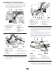
Figure50
1.Trim-lefthose4.Coverplate
2.Trim-righthose
5.Washer(5/16inch)
3.Clampsupport(right
swing-frameplate
location)
6.Bolt(5/16x2-3/4inch)
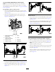
6.Atthetrailframe,securethetrim-leftandtrim-right
hoses(Figure48)withthe2clampblocks,bolt(5/16x
2-3/4inch),washer(5/16inch),andcoverplate,and
tightenthebolt(5/16x2-3/4inch)to1978to2542
N-cm(175to225in-lb).
7.Torquethehosettingsateachendofthetilt-down
(retract)hose,tilt-up(extend)hose,trim-lefthoseand
trim-righthoseto46to57N-m(34to42ft-lb)
9
InstallingtheHydraulicMotor
Hoses
NoPartsRequired
PreparingtoInstalltheHydraulicMotor
Hoses
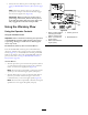
1.Attherearbulkheadofthemachine,removethe
2caps(1inch)fromthehydraulic-pressureand
hydraulic-returnttingsandthecap(5/8inch)from
thecase-draintting(Figure51).
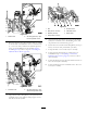
Figure51
1.Hydraulic-pressuretting
(1inch,portA)
6.Tube-elbow(3/4inch)
2.Case-draintting(5/8
inch)
7.Swiveltee(1x3/4x3/4
inch)
3.Hydraulic-returntting(1
inch,portB)
8.Checkvalve
4.Cap(1inch)9.45°elbowtting(3/4inch)
5.Cap(5/8inch)
24