
Installation Instructions


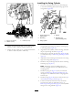


Figure33
1.Left-swingcylinderhose
2.Right-swingcylinderhose
8.Installthehosefromthettingintheright-swing
cylindertotheconnectorttinginportB7(Figure31,
Figure32,andFigure33).
9.Torquethehosettingsto20to28N-m(180to252
in-ft).
PurgingAirfromtheLiftandSwing
Cylinders
DANGER
Pressingtheelevationoatswitchortheswingoat
whileyouarebleedingthehydraulicsystemwill
causetheattachmenttomoveuncontrollablyand
mayresultinpersonalinjuryordeath,ordamage
theattachment.
Donotpresstheelevationoatswitchortheswing
oat(Figure34).
Figure34
1.Donotpresstheseswitches.
1.Ensurethattheareasurroundingthevibratoryplowis
clearofallpeopleandobjects.
2.Settheparkingbrakeandmovethecontrolsofthe
tractionunittotheNeutralposition;refertothe
Operator’sManualforthetractionunit.
3.Startthetractionunit;refertotheOperator’sManualfor
thetractionunit.
4.Pressbutton5ontheHomescreenofthecommand
centertotoggletothevibratoryplowfunction(Figure
35).
Figure35
1.Button5
5.Performthefollowingtopurgeairfromthelift
cylinder:
A.Movethebackllblade/vibratoryplowjoystick
rearwardtoraisethecradleandlowerlink(Figure
36).
Figure36
1.Backllblade/vibratory
plowjoystick
4.Swingleft
2.Raise
5.Swingright
3.Lower
B.Removetheliftingequipmentfromthetower
assembly.
C.Movethebackllblade/vibratoryplowjoystick
rearwardtoraisethecradleandlowerlink(Figure
36).
17