
Installation Instructions


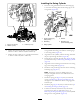


Figure22
1.Swingcylinder3.Pivotpin(swingcylinder)
2.Lower-snapring
6.Raisethepivotpinuntiltheswingcylinderisfreefrom
theforwardmountinglugs(Figure22).
Note:Useapieceoftapetoholdthepivotpinup.
7.Removetheswingcylinderandthe2washers(1-1/4
inch)fromtheswingframe(Figure23).
Note:Thesingcylinderweightsapproximately17kg
(38lb).
Figure23
1.Swingcylinder2.Washers(1-1/4inch)
AssemblingtheTowerand
CounterweightAssemblytothe
Machine
1.Threadalocknut(1inch)andwasher(1inch)ontothe
lowercenterbolt(1x8-1/2inch)thatyouinstalledin
step1ofAssemblingtheTowerandCounterweight
AssemblytotheMachine(page13);refertoFigure24.
Figure24
1.Bolt(1x8-1/2
inch)—centerRow-5
holeinthetower-mounting
plate
3.Washer(1inch)
2.Locknut(1inch)
Note:Movethetowerandcounterweightassembly
towardthemountingplateofthemachineasneededto
threadthenutontothebolt(Figure25).
Figure25
Machinewithtracksshown;alsoappliestoamachinewith
wheels
1.Towerandcounterweight
2.Mountingplate(machine)
2.Insert2bolts(1x8-1/2inch)intotheoutboardholes
inRow5andabolt(1x8-1/2inch)inthecenterslot
inRow1ofthetower-mountingplate(Figure26).
Note:Formachineswithwheel—threadthe2
outboardboltsintothenutsinthenutretainersthat
youinstalledinstep2of4PreparingtoInstallthe
TowerandCounterweightAssembly(page10).
13