
Operator's Manual


6
InstallingtheHydraulicHoses
Partsneededforthisprocedure:
1
Hose(34-1/2inch)
1
Hose(40-1/2inch)
1
Hose(47inch)
1
Cabletie
Procedure
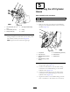
1.Removethe2caps(1inch)andthe1cap(5/8inch)
fromthebulkheadttingsinthehydraulic-attachment
panel(Figure20).
Figure20
1.Bulkheadtting
(pressure-hydrauliccircuit)
4.Hydraulic-attachment
panel
2.Bulkheadtting(case
drain)
5.Caps
3.Bulkheadtting
(return-hydrauliccircuit)
2.Installthepressurehose(88cmor34-1/2inch);
case-drainhose(119cmor47inch);andreturnhose
(103cmor40-1/2inch)betweenthettingsonthe
hydraulic-attachmentpanel(Figure21)andthettings
thatyouinstalledonthehydraulicmotorasshownin
Figure22.
Note:Ensurethattheangledttingonthepressure
hoseisconnectedtothebulkheadttingforthe
pressure-hydrauliccircuit.Alsoensurethattheangled
ttingonthereturnhoseisconnectedtothebulkhead
ttingforthereturn-hydrauliccircuitatthehydraulic
attachmentpanel.
Figure21
1.Bulkheadtting
(pressure-hydraulic
circuit—A)
5.Case-drainhose(119cm
or47inch)
2.Bulkheadtting(case
drain)
6.Returnhose(103cmor
40-1/2inch)
3.Bulkheadtting
(return-hydraulic
circuit—B)
7.Cabletie
4.Pressurehose(88cmor
34-1/2inch)
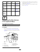
Figure22
1.45°elbowtting(3/4inch,
casedrain)
4.Pressurehose(88cmor
34-1/2inch)
2.90°anged-elbowtting(
pressure-hydrauliccircuit)
5.Case-drainhose(119cm
or47inch)
3.90°anged-elbowtting
(return-hydrauliccircuit)
6.Returnhose(103cmor
40-1/2inch)
3.Securethe3hydraulichoseswithacabletie(Figure21).
4.Torquethehydraulicttingsandhoses;refertothe
tablebelow:
13