
Operator's Manual


7.Removetheliftingequipment.
10
InstallingtheBoomHydraulic
Cylinder
Partsneededforthisprocedure:
1Boomhydrauliccylinder
1Boomcylindermountingpin
1
Hex-headbolt(3/8x1-1/2inch)
1
Locknut(3/8inch)
Procedure
Note:Ensurethatthefreeendoftheboomissupported
ontheoor.
1.Lubricatetheinsidediameteroftheupperholes
ofthecylindermountinglugwithgeneral-purpose,
lithium-basedgrease(Figure23).
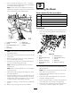
Figure23
Locknutisnotshown
1.Boom3.Boomcylindermounting
pin(1-3/4x3-3/4inches)
2.Cylindermountinglug(2)4.Hex-headbolt(3/8x1-1/2
inch)
2.Lubricatetheinsidediameteroftheholeinthe
piston-endttingofthehydrauliccylinderwithgrease
(Figure23).
3.Removetheplugsfromthecylinderandcoverthe
holeswithacleanrag.
4.Extendthepiston-endttingofthecylinderandalign
theholeinthettingwiththeholesintheboom
mountinghinges(Figure23).
Note:Residualhydraulicuidmayejectfromthe
cylinderports.
5.Securethepiston-endofthecylinderwithaboom
cylindermountingpin(1-3/4x3-3/4inches),a
hex-headbolt(3/8x1-1/2inch),andalocknut(3/8
inch)asshowninFigure23.
6.Lubricatetherod-endttingofthecylinderandboth
mountinglugsonthesideplatesoftheboom(Figure
23).
11
ConnectingtheHydraulic
PressureandReturnHoses
Partsneededforthisprocedure:
1
Hydraulichose(0.75x28.3inches)
1
Hydraulichose(0.75x29.4inches)
Procedure
1.Placeadrainpanunderthebulkheadttingsforthe
hydraulicpressureandreturncircuitsofthemachine
(Figure24).
Note:Thettingsarelocatedontheleftsideofthe
machinenearthefronttire(Figure24).
Figure24
1.Bulkheadttings(capped)
2.Removethecaponeachttingandlooselyinstalla
hydraulictting(3/4inch,90°elbow)ontoeachofthe
2bulkheadttingsasshowninFigure24.
Note:Retainthecapttingssothatyoucaninstall
themwhenyouremovethebackhoe.
16