
Operator's Manual


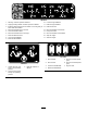


Table Of Contents
- NO TITLE
- .
- 1 Preparing to Install the Attachment onto the Machine
- 2 Installing the Backhoe Frame and Swing Tower onto the Machine
- 3 Installing the Backhoe Wiring Harness
- 4 Installing the Walkway to the Machine
- 5 Connecting the Controls to the Wiring Harness
- 6 Installing the Controls Cover and the Panels
- 7 Installing the Stabilizers
- 8 Installing the Stabilizer Hydraulic Cylinders
- 9 Installing the Boom
- 10 Installing the Boom Hydraulic Cylinder
- 11 Connecting the Hydraulic Pressure and Return Hoses
- 12 Bleeding the Stabilizer Cylinders
- 13 Connecting the Hydraulic Hoses to the Boom Hydraulic Cylinder
- 14 Bleeding the Boom Elevation Cylinder
- 15 Installing the Dipper
- 16 Installing the Dipper Hydraulic Cylinder
- 17 Installing the Bucket
- 18 Connecting the Hydraulic Hoses to the Dipper and Bucket Hydraulic Cylinders
- 19 Bleeding the Hydraulic System
- 20 Testing the Operator-presence Switch and the E-stop Switch
- 21 Lubricating the Stabilizers
- NO TITLE
- NO TITLE
- NO TITLE
- NO TITLE

ProcedureDescription
Qty.
Use
14
Nopartsrequired
–
Bleedtheboomelevationcylinder.
Dipper1
Dipperpivotpin(2x9-3/4inches)
1
Tabbedwasher1
Slotted-spannernut(1-3/4inch)
1
Retainerpin1
15
Greasetting
2
Installthedipper.
Hydrauliccylinder1
Dippercylinderpin(1-1/2x5.83inches)
1
Snapring
1
16
Retainerpin1
Installthedipperhydrauliccylinder.
Bucket1
Bucketpin2
Snapring
2
Bolt(3/8x1–1/2inch)
2
Lockwasher2
17
Locknut2
Installthebucket.
Hydraulichose(0.75x63.2inches)
1
Hydraulichose(0.75x65.6inches)
1
Hydraulichose(0.75x104.7inches)
1
Hydraulichose(0.75x108.9inches)
1
Anglestrap4
Hex-headbolt(5/16x3-1/4inch)
4
Washer(5/16inch)
8
18
Locknut(5/16inch)
4
Connectthehydraulichosestothe
boomhydrauliccylinder.
19
Nopartsrequired
–
Bleedthehydraulicsystem.
20
Nopartsrequired
–
Testtheoperator-presenceswitchand
theE-stopswitch.
21
Nopartsrequired
–
Lubricatethestabilizers.
Important:Ensurethatthereisadequatespacetomove
thestabilizersandthebackhoearmtofullextension
andthatthemachineandtheattachmentsareclearof
obstructions.
Note:Forillustrationsoftheattachmentinstalledonthe
tractionunit,refertoProductOverview(page27).
1
PreparingtoInstallthe
AttachmentontotheMachine
NoPartsRequired
Procedure
1.Parkthemachineonalevelsurface.
2.Lowertheattachment(s)totheground.
3.Stoptheengineandremovetheignitionkey.
7