
Installation Instructions


7
InstallingtheChassisFrame
Partsneededforthisprocedure:
4
Chassisframe
4Pivotaxle
4Pivot-axleplate
4
Spacer
4Retainingring
8
Bolt(16x60mm)
8
Locknut(16mm)
Procedure
1.Positionthechassisframesothatthetrackadjusters
arelocatedawayfromthecenterofthemachineas
showninFigure13andFigure14.
Note:Figure13andFigure14showonlytheouter
trackadjusters;theinnertrackadjustersarenotshown.
Note:Ensurethatthegreasettingsonthechassis
framefaceoutward.
1
g037595
Figure13
Forthefront,lefttrackandtherear,righttrack
1.Outertrackadjuster(2)
1
g037602
Figure14
Forthefront,righttrackandtherear,lefttrack
1.Outertrackadjuster(2)
2.Turnboththeinnerandoutertrack-adjusterbolts
(Figure15)sothattheadjustersmoveinward,making
iteasiertoinstallthetracklater.
g037597
1
Figure15
Onlytheoutertrackeradjusterisshown.
1.Track-adjusterbolt(2)
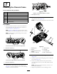
3.Installthechassisframeontotheframe-mountbracket
usingthepivotaxle(Figure16).
Note:Useahoisttoliftandpositionthechassisframe.
g037598
1
2
3
4
5
6
7
8
Figure16
1.Retainingring
5.Chassisframe
2.Spacer
6.Pivotaxle
3.Tubeoftheframe-mount
bracket
7.Pivot-axleplate
4.Locknut—16mm(2)8.Bolt—16x60mm(2)
4.Installthepivotaxleisfullythroughthechassisframe
(Figure16).
5.Installthespacerandretainingringontheendofthe
pivotaxle(Figure16).
6.Securetheoutsideendoftheaxlepivotwiththe
pivot-axleplate,2bolts(16x60mm)and2locknuts
(16mm).
Note:Torquethe2boltsand2nutsto255to311
N-m(188to230ft-lb).
7.Repeatthisprocedurefortheremaining3tracks.
11