
Installation Instructions


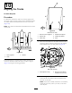


Figure19
Thenalsprocketthirdisnotshownforthepurposeof
clarity.
1.Spocketthird4.Nut(16mm)
2.Bolt(16x40mm)5.Onesetoffasteners—bolt
(1),washers(2),andnut
(1)
3.Washers
8.Checkthetensionofthetrack;referto11Checking
theTensionoftheTracks(page15).
9.Turnboththeinnerandoutertrack-adjusterbolts
outward(Figure20)thesameamountsothatthe
tensionacrossthetrackisequalwhileyousecurethe
trackinplace.
Forpropertension,thereshouldbeagapbetweenthe
bottomoftheframerailandtheinsideofthetrack
of8.3cm(3-1/4inches).
Figure20
1.Trackadjusterbolt(2)
2.Movethetrackadjuster
boltsevenlyoutward
10.Repeatthisprocedurefortheremaining3tracks.
9
CheckingandAdjustingthe
ToeoftheTracks
NoPartsRequired
Procedure
Note:Checktoensurethatthecenterlinesofthetrackson
eachaxleareapproximatelyparallel,withouttoe-inortoe-out.
Iftheyarenot,performtheprocedurethatfollows.
1.Placeawrenchontheatsurfacesonthetie-rodend
(Figure21).
g029074
1
2
3
4
Figure21
1.Threadedadjuster3.Holdawrenchhereonthe
tierodend.
2.Jamnut
4.Steeringlimiter
2.Useasecondwrenchtoloosenthejamnut(Figure21).
3.Movethesecondwrenchtotheatsurfacesofthe
threadedadjuster(Figure21)androtatethethreaded
adjusterinwardoroutwarduntilthetracksare
approximatelyparallel.
Note:Rotatethethreadedadjusterclockwiseto
shortenit;rotateitcounterclockwisetolengthenit.
4.Withtherstwrenchstillinplace,tightenthejamnut
securely.
5.Adjustthesteeringlimiter(Figure21)asneededto
preventthetrackfrominterferingwiththemachine.
Note:Thedistancefromthebaseofthecastingto
theendoftheboltshouldbeapproximately13.7cm
(5-3/8inches).
6.Lowerthemachinetotheground.
13