
Service Manual


Rear HOC
and
WPC Disassembly
(cont'd)
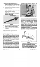
Figure
55
7.
If
further disassembly of the pivot arm is required,
remove the spring arm.
8.
Press the needle bearing and the oil
impregnated bushing from the pivot arm using
an arbor press.
9.
Removal of the grease
fitting
is not
recommended because
it
is pressed
in.
However,
if
damaged or
lost,
we suggest tapping
and installing a threaded grease fitting.
10. If the spring arm knob requires replacement,
push
in
on the detent tab, then pull the knob
straight
off.
NOTE: The detent rivet is not replaceable
separately.
Rear HOC
and
WPC Assembly
1.
2.
3.
4.
5.
6.
If
the grease fitting
in
the pivot arm has been
damaged or lost, tap and replace with a threaded
fitting.
Pack the caged needle bearing with grease then
press into the outside of the pivot arm until
it
is
flush with the groove that houses
the
externally
tabbed thrust washer.
Press the oil impregnated bushing into the boss
on the pivot arm until
it
is flush with the face of
the boss. See Figure
56.
If
spring arm disassembly was required, install
the knob making sure that the detent is pressed
out about 1.5 mm
(.060'”).
Install the spring arm
knob
so
that the concave side of the knob and
the convex side
of
the rivet align.
Assemble the spring arm and pivot arm as shown
in
Figure
58.
To increase service life, make sure all parts are
clean prior to assembly and coated with new
grease.
Self-Propel System
40
_-
Figure
56
7.
If removed, install new O-rings
in
the innermost
groove
5.7
cm (2-1/4”)
in
from end on each end,
making sure that
it
is fully seated
in
the groove.
See Figure
58.
8.
Slip the end cap onto the output shaft
but
do not
9.
Slide the pivot arm and spring arm assembly
onto the output shaft, boss first.
NOTE: The convex side of the spring arm rivet
and the concave side of the knob on the spring
arm should both be facing the housing.
10.
Slide the externally tabbed thrust washer and the
internally tabbed thrust washer onto the output
shaft. (Make sure that the tab on the internally
tabbed thrust washer follows the contour
of
the
keyway.) Secure with the special retaining clip,
making sure that the center tab
fits
properly into
the keyway. This will prevent rotation of the clip
on the output shaft.
fasten at this time.
11. Place the friction ring into the groove on the pivot
arm, flat side out.
12.
Slide the clutch washer onto the shaft
so
that the
recesses for the key are facing out.
13. Place the wheel pinion key
in
the groove on the
output shaft with the leg toward the clutch
washer.
NOTE: There is a left and a
right
wheel pinion
key. You are using the correct key
if
when placed
in
the groove, the top of the key is flat and the
straight portion of the leg is perpendicular to the
shaft.
Before assembling further, rotate the clutch washer
back and forth slightly, making sure that the key
actuates properly. See Figure
57.
Vacu-Power Mower
n
n
n