
Installation Instructions


and 4 flang e n uts (3/4 inc h) while aligning the
mounting holes with the holes in the batter y
tra y ( Figure 5 ).
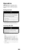
Figure 5
1. Lift cylinder support 4. U-bolt
2. Right end of the axle 5. Carriage bolt, 3/8 x 3/4
inch
3. Rear frame battery tray 6. Flange nut, 3/4 inch
4. Secure the lift cylinder suppor t to the rear
frame with 2 car riag e bolts (3/8 x 3/4 inc h)
and 2 flang e n uts (3/8 inc h). Tighten the 4
flang e n uts on the U-bolts equally to mak e sure
the brac k et is aligned to the axle . Tighten the
tw o n uts securing the rear of the brac k et to the
rear frame ( Figure 5 ).
5. Mount the bottom end of the lift actuator to
the lift cylinder suppor t with a clevis pin and
cotter pin. P osition the components as sho wn
in Figure 6 .
Figure 6
1. Actuator
3. Clevis pin
2. Lift cylinder support
4. Cotter pin
4