
Service Manual


I
34
34
I
GN
IT
I
ON
SYSTEM
1.
Set multimeter selector switch to
R
x
position.
2.
Check resistance between terminal
(A)
and case
(B).
If resistance
is
out of specified value, replace control
unit.
C
A
U
T
I
0
N
:
Do
not use Megger.
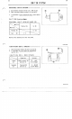
.CONTROL UN IT RES
I
STANCE
Terminal
(A)
Case
(B)
Case
(B)
N
0
T
E
:
This check may not cover every defect.
r
1.
Check resistance between the points as specified.
2.
If resistance
is
out
of
specified value, replace
ignition coil.
IGNITION COIL RESISTANCE
Connect ion
Primary
Primary terminal
(A)
coil
Secondary
and Core (C)
and Core (C)
coi
1
Plug lead
(B)
Resistance
0.67
(R
x
Range)
6.0
(R
x
Range)
E30FCOSW2
EBOFC
I
OW2