
Service Manual


60
60
GOVERNOR
1.
Check governor gear assy for wear and damage, as in-
stalled in crankcase cover.
C
A
UT
I
0
N
:
Do
not remove governor gear assy from crank-
case cover exceot to reolace~
If
once removed.
it
cannot be
re-used.
2.
If governor gear assy
(A)
must be replaced, remove
it
with proper size screw drivers
(B).
C
A
U T
I
0
N
:
Do
not damage gasket surface by screw
drivers.
1.
Place sleeve
(A)
into governor gear assy
(B).
C
A
UT I
0
N
:
Sleeve can not be assembled after governor
gear assy installed in crankcase cover.
2.
Place thrust washer (C) on boss of shaft
(D)
and then
install governor gear assy
(B)
with sleeve
(A)
to shaft
until1 step
(E)
fits into groove
(F).
3.
Check free rotation of governor assy after installation.
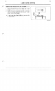
1.
Install governor shaft
(A)
into crankcase and set lock-
ing pin
(B)
to governor shaft positioning as shown.
NOT
E
:
Be careful for position of locking pin end and
projection (C) which
is
stopper of governor shaft
(A).
E39FC04W2
E39FCOZWI
E39PCOSYI