
Service Manual


47
GTS 200
Lubrication
Lubrication
Contents
Extended Oil Fill and Dipstick
47
. . . . . . . . . . . . . . . . . . . . . .
Breather 47
. . . . . . . . . . . . . . . . . . . . . . . . . . . . . . . . . . . . . . . .
Remove Breather
47
. . . . . . . . . . . . . . . . . . . . . . . . . . . . . . . . .
Install Breather V
alve 47
. . . . . . . . . . . . . . . . . . . . . . . . . . . . . .
Remove Oil Pump
47
. . . . . . . . . . . . . . . . . . . . . . . . . . . . . . . .
Inspect Oil Pump
48
. . . . . . . . . . . . . . . . . . . . . . . . . . . . . . . . .
Install Oil Pump
48
. . . . . . . . . . . . . . . . . . . . . . . . . . . . . . . . . .
Install Pump Cover
48
. . . . . . . . . . . . . . . . . . . . . . . . . . . . . . .
Install Oil Filter Adapter
48
. . . . . . . . . . . . . . . . . . . . . . . . . . .
Extended
Oil Fill and Dipstick
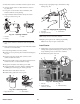
The
GTS 200 uses a plastic extended oil fill tube and a quarter
turn screw-on-dipstick.
Dipstick oil fill tube is pressed into crankcase cover
.
1
2
3
Fig. 110 – Oil Fill and Dipstick
1. Dipstick
2. Oil
fill tube
3.
“O” ring
Breather
The
GTS 200 engine uses a breather valve to control and
maintain a partial vacuum in the crankcase.
The breather valve is a fiber disc or reed valve which closes
on the piston’
s up stroke and opens on the piston’
s down
stroke to keep a partial vacuum in the crankcase.
This partial vacuum prevents oil leakage past piston rings,
valve guides, oil seals, governor lever shaft and gaskets.
Remove Breather
1. Before
breather can be removed, remove fuel tank,
extended oil fill tube, blower housing, flywheel, and
muffler.
2. Remov
e t
w
o s
crew
s h
oldin
g b
reather t
o c
ylinder
, F
ig
.
111.
3.
Remove four screws holding breather passage cover and
gasket, Fig. 1
11.
2
1
1
3
Fig. 111
– Removing Breather and Breather
Passage Cover
1. Gasket
2. Breather
passage cover
3. Breather
Install
Breather V
alve
1. Install
new breather passage gasket and breather passage
cover on cylinder channel and torque four (4) screws to
30 in. lbs. (3.0Nm).
2.
Place new breather gasket and breather on cylinder and
install two (2) screws torquing screws to 65 in. lbs.
(7.0Nm), Fig. 1
11.
Gaskets do not require any sealant.
Remove
Oil Pump
(on models so equipped)
1. Oil
pump can be removed without removing sump from
engine.
2.
Remove three screws and remove pump cover and “O”
ring, Figs. 1
12 and 1
13.
3.
Carefully remove inner and outer rotors.
1
Fig. 112
– Removing Pump Cover
1. Oil
pump cover