
Operator's Manual


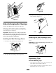


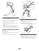

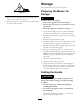

Figure46
1.1to1-1/2inches(25to38
mm)
4.Cablesupportnut
2.Self-propeldrivebar5.Cablesupport
3.Cablejacket
2.Holdtheself-propelbail1to1-1/2inches(25to38
mm)fromthehandle(Figure46).
3.Pulldownthecablejacket(towardthemower)until
thereisnoslackinthecable(Figure46).
4.Tightenthenutonthecablesupport.
5.Releasetheself-propeldrivebarandensurethatthe
cableisloose.
Note:Thecablemustbeloosewiththeself-propel
drivebarinthereleasedposition;otherwise,the
mowermaycreepwhenthebarisdisengaged.
AdjustingtheSelf-propelDrive
Model20999only
Ifyourmowerdoesnotself-propelproperly,adjustthe
self-propeldrivecable.
1.Loosenthenutonthecablemount(Figure47).
G009696
1
Figure47
1.Cablemount
2.Pulltheupperhandlebackfullyrearward.
Note:Ifthehandledoesnotmovesmoothly,refer
toLubricatingtheUpperHandle.
3.Pullthecablejacketdownwarduntilyouremovethe
slackintheexposedcable(Figure48).
Figure48
1.Exposedcable
4.Pushthecablejacketupward1/8inch(3mm).
Note:Youcanplacearuleragainsttheupperside
oftheblackcablemountandmeasurehowfarthe
upperendofthecablejacketmoves(Figure49).
18