
Service Manual


Flywheel Brake Operation
(if
installed)
Zone start mowers are fitted with a flywheel brake that kills
the ignition and stops
the
rotation of the engine. The brake
is a spring loaded lever that when released causes a brake
shoe to rub against the flywheel in a self energizing
manner. An arm on the brake lever at the same time
touches a contact point that is part of the ignition kill wire
terminal. This will ground the kill wire to prevent spark. To
start the engine, the brake cable
is
pulled to both open
electrical contact and pull the brake shoe away from the
flywheel.
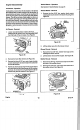
Flywheel Brake Removal (if Installed)
1.
Unload the spring with a spring hook.
2.
Remove the cable.
3.
Disconnect the ignition kill wire.
4.
Remove the two
5/16"
hex, washer head screws that
retain the brake assembly to the block of the engine.
See Figure
40.
Figure
40
Fuel lank Operation
See Section
2
on Fuel System, page
23.
Fuel lank Removal
Crimp the fuel hose with a pair of locking pliers.
2.
Remove the hose clamp on the carburetor end of the
hose.
CAUTI0N
:
A
Avoid fire and explosion, store fuel
in a container designed for gasoline and never smoke
while working around gasoline.
3.
Release the clamping pliers and drain the fuel into a
container designed to receive gasoline.
4.
Remove the two
3/8"
hex, washer head screws
(1-1/4"
long) retaining the fuel tank to the engine.
5.
The
75
micron fuel filter screen is an integral part of the
fuel tank and is not removable.
GTS
150
31
Muffler Operation
The muffler quiets exhaust noise by slowing the escape of
combustion gases while at the same time preventing
excessive back pressure. The muffler is of a dual chamber
design with the exhaust being discharged into the first
chamber and then through a series of holes into the
second chamber where the exhaust is discharged to the
atmosphere.
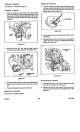
Muffler Removal
1.
Remove the
two
3/8"
hex, washer head cap screws
that retain the exhaust pipe to the engine.
2.
Remove the single
3/8"
hex, washer head cap screw
that retains the muffler bracket to the block of the
engine. See Figure
41.
Figure
41
3.
Remove and discard the gasket between the exhaust
pipe and the engine.
Dipstick and Oil
Fill
lube Removal
Remove the two
3/8'
hex, washer head screws that
retain the dipstick tube.
2.
Withdraw the tube from the block of the engine. The
tube is sealed with an
"0"
ring. See Figure
42.
Figure
42
Engine