
Service Manual


43
GTS 200
Electric
Starter
3. Three
(3) screws holding gear cover and gear itself may
now be removed.
4.
Lift clutch assembly and pinion gear of
f their respective
shafts.
5.
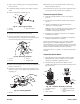
Remove starter motor thru bolts, Fig. 97.
1
2
3
Fig. 97
– Removing Thru Bolts
1. Housing
2. End
cap
3.
Remove thru bolts
6. Separate
motor end cap from motor housing.
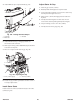
7.
Push motor armature out through bottom of starter
housing, taking care to slide plastic mounted terminal out
of motor housing along with end cap, Fig. 98.
1
4
3
2
Fig. 98
– Removing Armature
1. Terminal
2. End
cap
3. Housing
4.
Armature shaft
8. Before
removing armature from end cap, check brushes for
freedom of movement.
9.
If brushes are found to be sticking in their retainers, this
must be corrected, or poor starter motor performance will
result, Fig. 99.
1
5/64”
(2mm)
Fig. 99
– Checking Brushes
1. Brushes
10. If
brushes are worn to a length of 5/64” (2mm) or less,
brushes should be replaced.
11. Chec
k b
rus
h s
pring
s f
or proper tension (sufficient force
t
o k
ee
p b
rus
h i
n fir
m c
ontac
t w
it
h c
ommutator).
Clean and Inspect Starter
1. Clean
all dirt from armature, end cap, motor support,
gears, etc.
2.
End cap bearings and armature should not be soaked in a
solvent.
3.
Armature commutator may be cleaned with a fine
sandpaper or commutator paper
.
Note:
Do not use any metallic oxide paper or emery cloth,
as metallic oxide or emery will become embedded in
commutator causing rapid brush wear
.
4.
If armature is suspected to be defective, a new armature
should be tried in motor
.
5.
If proper testing equipment is available, check suspected
armature to determine if it is defective.
Starter motor armatures have very low resistance, usually
below detection on available multimeters. T
o check for
shorted armatures, a piece of equipment known as a “growler”
may be used. If this equipment is not available, a known good
armature should be tried and performance rechecked.
If magnets are loose or cracked, a new motor housing should
be tried.
Assemble Starter Motor
1. When
all parts have been thoroughly inspected, lightly
lubricate bearings with an oil made for use in electric
motors and reassemble in following manner
.
2.
Insert brush springs and brushes in holders as far as
possible, and hold them in this position with tool shown in
Figs. 89 and 100.
1
3
2
1
5
4
.225”
(5.72mm)
.200”
(5.1mm)
Fig. 100
– Armature Assembly to End Cap
1. Gray
plastic washers
2. Armature
3.
Brush spreader
4.
.176” (4.47mm) thick fiber
washer
5.
.030” (.76mm) thick steel
washer