
Service Manual


58
GTS 200
Cylinder
and Bearings
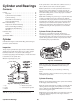
2. Press
bearing to dimension shown in T
able No. 7, page 58
and Fig. 144.
1
3
2
Fig. 144
– Pressing Bearing
1. Bushing
driver bearing
2. Bearing
3.
Cylinder support
3. Stake
b
earin
g a
s s
hown
, F
igs
.
14
3 a
n
d
145.
1
Fig. 145
– Staking Bearing
1. Staked
Oil Seals
Always
i
nstal
l n
e
w o
i
l s
eal
s w
heneve
r e
ngin
e i
s d
isassembled for
majo
r s
ervicin
g o
r w
hen replacin
g b
earings
. W
he
n i
nstalling
crankcas
e c
over o
r s
ump
, a
lway
s u
s
e t
h
e c
orrec
t s
ea
l p
rotector to
preven
t d
amagin
g o
i
l s
eal, Table
No.
3.
Crankcase
Sump
Install
Use
B
rigg
s & S
tratto
n T
oo
l #
19356
, S
ea
l P
rotecto
r K
it,
Table
No.
3, t
o p
rotec
t o
i
l s
ea
l w
he
n i
nstallin
g c
rankcas
e c
over
o
r s
ump
. D
o n
ot forc
e c
over o
r s
ump
. M
ak
e s
ur
e m
echanical
governor gea
r a
n
d o
i
l p
ump (whe
n u
sed) i
s e
ngage
d w
it
h c
am
gear.
1.
For adjustment procedure for crankshaft end play see
Crankshaft and Camshaft, page 55.
2. T
orque crankcase cover screws in sequence shown in
Fig. 146.
1
2
3
4
5
6
7
Fig. 146 – T
orque Sequence
Specification
T
ables
Table No. 3
Seal Protectors
Briggs
& Stratton
Tool #
Color
Crankshaft
Journal Size
19334/5 Brown
1.062”
(26.97mm)
Table No. 4
Standard Bore Diameter
Maximum Inches
Minimum Inches
2.6885” 2.6875”
2
.
6885
(68.288mm)
2
.
6875
(68.263mm)
Table No. 5
Cylinder Bearing Reject Size Chart
Magneto
Bearing
PTO
Bearing
.878” 1.065”.
878
(22.30mm)
1
.
065
(27.05mm)
Table No. 6
Camshaft Bearing Reject Sizes
Inches
Millimeters
Gauge
#
.504”
19164
.
504
(12.80mm)
19164
Table No. 7
DU Bearing Depth
Depth Mag.
Depth PT
O
.080”.
080
(2.03mm)
–
Table No. 8
Crankcase Sump Torque
In. Lbs.
Nm
110
110
(12.0)