
Service Manual


Pivoting Zone Start Brake Disassembly
(cont'd)
Note:
Numbers in parentheses in the following
procedures refer to Figure 82 on previous page.
1.
If
the engine and blade are taking more than
3
seconds to stop when the blade control bail is
released
,
inspect the brake pad for excessive
wear and replace
if
necessary. Note that the
brake pad and the brake plate are replaceable
only as an assembly.
2. To reduce the pressure
of
the spring between
brake mounting plate (10) and brake plate (8),
squeeze tabs of brake cable that hold it in place
at the brake mounting plate. Push cable through
the hole in brake mounting plate.
3.
Slide cable out through horizontal slot in brake
mounting plate. Also, slide the ball end of the
cable up through the vertical slot in the brake
plate.
Note:
In step
4,
some units may use a
3/8
head with
1/4"
diameter screw (rather than a
10 mm).
remove the brake plate and brake pad attached
to it.
5.
If
the ground strap or any part of this assembly
4.
Remove the 10 mm shoulder screw (7) to
requires replacement, remove the second screw
(9) to remove the brake mounting plate from
the engine.
Pivoting Zone Start Brake Assembly
1.
If
the brake mounting plate was not removed
from the engine, simply reconnect the grounding
lead to the push-on terminal directly above the
ground strap stop
(4)
and continue with the
reassembly process.
Note:
If
the brake mounting plate was removed,
tighten screw (9) to 60 70 in Ibs (6.78 7.91
N-m)
2. Secure the replacement brake plate to the
engine with shoulder screw (7). Tighten it to 90
in Ibs (9.2 N-m) Ensure that the brake plate
pivots freely.
3.
Slide the cable into the narrow slot on the brake
mounting plate and then push the cable into the
hole making sure the tabs lock into the bracket.
4.
One end
of
the compression spring has a hook
shape to
it;
that end hooks over an indentation
in the brake plate. Squeeze the compression
spring and slip it over the cable between the
brake mounting plate and brake plate.
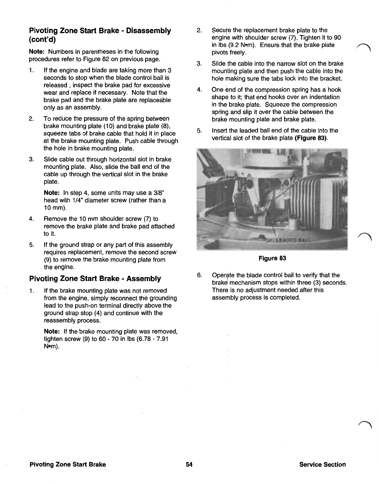
5.
Insert the leaded ball end of the cable into the
vertical slot of the brake plate
(Figure 83).
Figure 83
6. Operate the blade control bail to verify that the
brake mechanism stops within three
(3)
seconds.
There is no adjustment needed after this
assembly process is completed.