
Service Manual


TESTING ELECTRICAL COMPONENTS
4 - 8 Carefree Mower Service Manual
Switch Testing
Switch Testing (battery powered models)
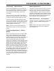
The switch used is a two position, three terminal
switch. Two tests must be made to assure the switch
works properly. An ohmmeter or continuity light will
properly test this switch. Continuity must be present as
shown in the diagram (Fi
g
ure 48).
Figure 48
plug
Wire Harness
The wire harness on battery powered models does not
contain any special components, such as diodes.
Wires can be tested for continuity in a normal manner.
Possible failure modes include broken wires, loose
terminals, or damaged insulation.
Wiring diagrams are located on the underside of the
hood (motor cover) and in the parts catalog. Be sure to
use the diagram for your specific model.
Testing Safety Key Terminals
Test by checking for 24 or 36 volts between both
terminals with the key removed and the control bar in
the ON position (Figure 49).
NOTE:
The charge
remaining indicator will light. (It is not necessary to
remove any connectors for this test.) Assure the circuit
breaker is closed for this test.
NOTE:
The safety key handles hi
gh current. A poor
connection could result in burnt terminals.
Important
— Do not distort connectors by forcing test
probes into them.
Figure 49
0674-011
Circuit Breaker Testing
Test the circuit breaker (Figure 50) with an ohmmeter
for continuity. It should be continuous.
NOTE:
The circuit breaker is a push to reset type.
Figure 50
5306-115
Position 1 Position 2
B + C continuity B + A continuity