
Service Manual


E
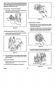
INSULATOR
CHAMPION
RC12YC
a
.OW"
(.76
mm)
Figure
23
There are two critical areas important to proper spark plug
function. The first is that the electrodes are properly
gapped and are clean. This ensures that a strong spark will
be present and that
it
occurs at the proper time. Excessive
gap or fouling can delay firing enough to cause a
loss
of
power or stalling. Correct gap is
.030" (.76
mm).
The other important area is the insulator. The insulator
prevents arcing from taking place in another area of the
plug, away from the electrodes. Because of the extremely
high voltage present, even a slight crack or fouling of the
head insulator can result in arcing and a malfunction of the
Plug-
Armature Coil Wiring
-
Operation
The armature coil has two external wires. One wire is the
high voltage spark plug wire and the other wire is the
primary grounding or engine kill wire. The free end of the
kill wire is terminated at the throttle bracket kill terminal.
There are two ground terminals that connect to the frame
of the armature coil and through the armature coil frame to
the block of the engine.
Air Gap Adjustment
1.
Remove the gas cap.
Use extreme care if there is fuel in the
gas tank.
Do
not smoke or allow open flames around
gasoline. Gasoline fumes are explosive.
2.
Remove the four
3/8"
hex, washer head screws that
retain the blower housing.
on the fuel tank.
3.
Remove the blower housing and replace the gas cap
4.
Loosen the two screws that retain the ignition arma-
ture coil. Use a feeler gauge to set the air gap between
the flywheel and ignition armature coil to
.008
-
.012."
(.20
-
.30
mm)
Ignition
26
5.
Tighten the
5/16"
hex, washer head screws retaining
the armature coil to
45
in
Ibs
(5Nm).
6.
Remove the gas cap and replace the blower shroud.
The blower shroud fasteners are tightened to
50
in
Ibs
(5.6Nm).
7.
Install the gas cap.
Ignition Armature Coil Removal
1.
Remove the gas cap.
CAUTION:
extreme care
if
there is fuel in the
gas tank. Do not smoke or allow open flames around
gasoline. Gasoline fumes are explosive.
2.
Remove the four
3/8"
hex, washer head screws that
retain the blower housing.
on the fuel tank.
3.
Remove the blower housing and replace the gas cap
4.
Disconnect the armature coil secondary ground wire
(igniton kill wire) from the grounding terminal on the
throttle control bracket.
5.
Unplug the spark plug wire.
6.
Remove the
two
5/16"
hex, washer head screws that
retain the armature coil. The armature coil may now be
removed from the engine.
Ignition Armature Coil Testing
Use an approved tester to test armature coils. Coil speci-
fications are supplied by the tester manufacturer or can be
found in Briggs and Stratton form
MS-7862,
"Instruction
Book
for Testing Briggs Stratton Ignition Coils."
1.
The primary coil should have
.2
to
.4
ohms of resis-
tance. The secondary coil should have
2400
to
5000
ohms of resistance.
2.
Primary resistance is measured between the kill wire
and ground. Because the primary resistance
is
so
small the resistance measurement will more realisti-
cally be used for disclosing either short circuits or,
more likely, open circuits
in
the primary winding.
3.
Secondary resistance is measured between the spark
plug wire and ground.
Ignition Armature Coil Installation
I.
Lightly tighten the
two
screws that retain the ignition
armature coil. Use a feeler gauge to set the air gap
between the flywheel and ignition armature coil to
.008
-
.012."
(.20
.30
mm)
2.
Tighten the
5/16"
hex, washer head screws retaining
the armature coil to
45
in
Ibs (5Nm).
3.
Remove the gas cap and install the blower shroud.
The blower shroud fasteners are tightened to
50
in
Ibs
(5.6Nm).
4.
Install the gas cap.
GTS
150
.~