
Operator's Manual


19
2.
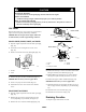
Remove the knob and side cover clamp (Fig. 31).
m–4275
1
2
3
Figure
31
1. Knob
2. Side
cover clamp
3.
Side opening cover
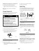
3. Remove
and save the three bolts securing the
dischar
ge cover to the mower (Fig. 32). Save the cover
and bolts for future use.
m–4275
3
2
1
Figure
32
1. Discharge
cover
2.
Bolt (3)
3.
Screw and nut
4. Remove
the screw and nut from side of the mower
(Fig. 32). Save them for future use.
5.
Install four grommets supplied with the grass catcher
into the four square holes in the mower (Fig. 33).
2009
1
Figure
33
1. Grommet
(4)
6. Insert
the tongue of the discharge tunnel into the
mower (Fig. 34).
7.
Align the holes in the tunnel with the grommets in the
mower (Fig. 34).
8.
Ensure that the hole in the tongue aligns with the hole
in the side of the mower (Fig. 34).
2010
3
5
2
4
4
1
Figure
34
1. Discharge
tunnel
2. Tongue
3.
Self-tapping screw
4.
Bolt (3)
5.
Discharge tunnel door
9. Install
the self-tapping plastite screw supplied with the
grass catcher into the side hole and tongue, and
partially tighten the screw (Fig. 34).
10.
Using three screws supplied with the grass catcher
,
fasten the dischar
ge tunnel to the mower (Fig. 34).
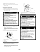
11.
Secure the front, right corner of the dischar
ge tunnel
and the side opening cover with the side cover clamp
removed previously and the long knob supplied with
the grass catcher (Fig. 35)
m–4274
1
2
3
Figure
35
1. Long
knob
2.
Side cover clamp
3.
Side opening cover
DANGER
POTENTIAL
HAZARD
•
If the side opening cover is not secur
ely
clamped in place, debris could be thr
own out of
the side opening.
WHA
T CAN HAPPEN
• Thr
own debris can cause serious personal
injury or death to the operator or bystanders.
HOW T
O A
V
OID THE HAZARD
•
Always ensur
e that either the side opening
cover is closed and locked in place by the side
cover clamp or that the side discharge chute is
secur
ely seated in place befor
e starting the lawn
mower.