
Operator's Manual


20
2010
3
5
2
4
4
1
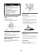
Figure
38
1. Discharge
tunnel
2. Tongue
3.
Self-tapping screw
4.
Bolt (3)
5.
Discharge tunnel door
9. Install
the self-tapping plastite screw supplied with the
grass catcher into the side hole and tongue, and
partially tighten the screw (Fig. 38).
10.
Using three screws supplied with the grass catcher
,
fasten the dischar
ge tunnel to the mower (Fig. 38).
11.
Secure the front, right corner of the dischar
ge tunnel
and the side opening cover with the side cover clamp
removed previously and the long knob supplied with
the grass catcher (Fig. 39)
m–4274
1
2
3
Figure
39
1. Long
knob
2.
Side cover clamp
3.
Side opening cover
DANGER
POTENTIAL
HAZARD
•
If the side opening cover is not secur
ely
clamped in place, debris could be thr
own out of
the side opening.
WHA
T CAN HAPPEN
• Thr
own debris can cause serious personal
injury or death to the operator or bystanders.
HOW T
O A
V
OID THE HAZARD
•
Always ensur
e that either the side opening
cover is closed and locked in place by the side
cover clamp or that the side discharge chute is
secur
ely seated in place befor
e starting the lawn
mower.
12. T
ighten all four screws and the long knob.
13.
Open and close the tunnel door to ensure that it moves
freely (Fig. 38).
Installing the Grass Bag
Note: T
o recycle grass instead of catch it, do not install
the grass bag and ensure that the dischar
ge tunnel door is
closed and secured.
DANGER
POTENTIAL HAZARD
• Thr
own objects may r
esult if the discharge
door does not close completely
.
WHA
T CAN HAPPEN
• Thr
own objects can cause serious personal
injury or death.
HOW T
O A
V
OID THE HAZARD
•
If the discharge door cannot be closed because
grass clippings clog the discharge ar
ea, stop the
engine and gently move the discharge door
handle back and forth until the door can be
closed completely
. If door still cannot be closed,
r
emove the obstruction with a stick; not your
hand.
1.
Stop the engine and wait for all moving parts to stop.
2.
Ensure that the dischar
ge door handle is fully forward
(door closed) (Fig. 40).