
Installation Instructions


13
InstallingtheFuelPumpon
aZMasterMachine
Partsneededforthisprocedure:
1Fuel-pumpbracket
1Fuelpump
1
Fuellter
4Hoseclamp
2
Bolt(1/4x5/8inch)
2
Nylonlocknut(1/4inch)
1Hose
Procedure
Thisprocedureisformachineswiththefollowing
modelnumbers.
MachineModelNumber
ZMaster7000,52inchcutting
unit
72266
ZMaster7000,60inchcutting
unit
72267
ZMaster7000,72inchcutting
unit
72274
ZMaster7000,132cmcutting
unit
72264TE
ZMaster7000,152cmcutting
unit
72265TE
ZMaster7000,132cmcutting
unit
72279TE
ZMaster7000,72inchcutting
unit
74274
ZMasterZ595,72inchcutting
unit
74274CP
ZMaster7000,60inchcutting
unit
74267
ZMaster580D,60inchcutting
unit
74267CP
ZMaster7000,52inchcutting
unit
74266
ZMaster580D,52inchcutting
unit
74266CP
ZMaster7000,132cmcutting
unit
74279TE
ZMaster7000,152cmcutting
unit
74265TE
ZMaster7000,132cmcutting
unit
74264TE
UseFigure1,Figure14,Figure15,andFigure16for
thisprocedure.
Note:Installthefuellterwiththearrowpointing
towardsthefuelpump.
1.Beforeremovingtheexistingpump,clampthe
fuelhoseonbothsidesofthepump.Thiswill
preventfuelleakingwhenreplacingthepump.
2.Removetheexistingfuelhosesfromthefuel
pump.
3.Removetheexistingfuelpumpfromthemachine
anddiscardthehardware.
4.Forinternationalmachinesonly,locate,mark,
anddrillahole(9/32inch)intotheguardas
showninFigure14andFigure16.
WARNING
Usingadrillwithoutpropereye
protectionmayallowdebristoenterthe
eye,causinginjury.
Whendrilling,alwaysweareye
protection.
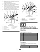
g368846
Figure14
1.9/32inchhole2.63.5mm(2-3/8inches)
5.Fordomesticmachines,installthenewfuel
pumpusingthebottomholeinthepumpwith
abolt(1/4x5/8inch)andalocknut(1/4inch);
refertoFigure15.Onlyonenutandboltisused
fordomesticmachines.
6.Forinternationalmachines,installthenewfuel
pumpusingbothholesinthepumpandsecure
itwith2bolts(1/4x5/8inch)and2locknuts(1/4
inch);refertoFigure16.
7.Installahoseclampontotheexistingfuelhose
fromthewaterseparatorandinstallitontothe
newfuelpump.Secureitwiththehoseclamp.
16