
Installation Instructions


6.Routethe9inchhosethroughthe1-holetabon
thevalvebrackettotheremaininginletonthe
vacuum-controlvalve.
7.Securethe9inchhosetothevacuum-control
valvewithahoseclamp(13/32).
8.Connectthelooseendofthe9inchhosetothe
smallendofastraighttting(3/16to1/4inch)
withahoseclamp(13/32inch).
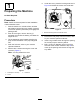
9.Securethevalvebracketassemblytothe
supportbarthatextendsfromtheframewitha
cabletie(Figure5).
g302540
Figure5
1.Hoseclamp(13/32inch)3.Cabletie
2.9inchhose
4.Smallendofstraighttting
(3/16to1/4inch)
4
CompletingtheInstallation
Partsneededforthisprocedure:
1
Hose(10-1/2inches)
1
Hose(9-1/2inches)
1
T-tting(1/2x1/2x5/16inch)
1
T-tting(1/4x1/4x1/4inch)
4
Hoseclamp(1/2inch)
2
Hoseclamp(5/16inch)
2
Hoseclamp(13/16inch)
1Fuelcap
Procedure
1.Connectthe10-1/2inchhosetothestraight
ttingonthe9inchhosefromthevacuum-control
valveandsecureitwithahoseclamp(1/2inch).
2.Connectthelooseendofthe10-1/2inchhose
tothecenterbranchofthe1/4x1/4x1/4inch
T-ttingandsecureitwithahoseclamp(1/2
inch).
3.Connectthe9-1/2inchhosetothestraighttting
ontheupperhosefromthevacuum-control
valveandsecureitwithahoseclamp(5/16
inch).
5