
Installation Instructions


InstallingtheCenterSpray-Valve
Connector
1.AlignthewireinsulationcolorsoftheDINharnessto
thewireinsulationcolorsofthe3-pinadapterforthe
centersprayvalveasshowninthewiretableforthe
centersprayvalve.
WiringTable—CenterSprayValve
Wirecolorcodes—DINwire
harness
Wirecolorcodes—3-pin
adapter
BrownPink
BlueBlack
Yellow/green
White
2.InsertthewireoftheDINwireharnessintothe
butt-spliceconnectorofthe3-pinadapter
3.Centerthecrimpingtooloverthebutt-spliceconnector
andwiresandcrimptheconnectorsecurely.
4.Repeatsteps2and3forthe2remainingwires.
5.Useaheatguntoshrinktheinsulatingsleevesofthe
3butt-spliceconnectors.
InstallingtheLeftSpray-Valve
Connector
1.AlignthewireinsulationcolorsoftheDINharnessto
thewireinsulationcolorsofthe3-pinadapterforthe
leftsprayvalveasshowninthewiretablefortheleft
sprayvalve.
WiringTable—LeftSprayValve
Wirecolorcodes—DINwire
harness
Wirecolorcodes—3-pin
adapter
BrownPink
BlueBlack
Yellow/green
White
2.InsertthewireoftheDINwireharnessintothe
butt-spliceconnectorofthe3-pinadapter
3.Centerthecrimpingtooloverthebutt-spliceconnector
andwiresandcrimptheconnectorsecurely.
4.Repeatsteps2and3forthe2remainingwires.
5.Useaheatguntoshrinktheinsulatingsleevesofthe
3butt-spliceconnectors.
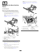
InstallingtheRate-ValveConnector
1.Cutoffthebutt-spliceconnectorsforthepinkwire
andblackwiresofthe4-pinadapter(Figure37).
Figure37
1.4-pinadapter3.Pinkwire
2.Blackwire4.Butt-spliceconnector
2.Strip8mm(5/16inch)ofinsulationfromthepinkand
blackwiresofthe4-pinadapter(Figure38).
Note:Youwillconnectthepinkandblackwiresof
the4-pinadapterinInstallingtheMaster-SprayValve
Connector(page22).
Figure38
1.Blackwire(4-pinadapter)3.Removedsectionofwire
insulation—8mm(5/16
inch)
2.Pinkwire(4-pinadapter)
3.AlignthebrownwireoftheDINharnesswiththegray
wireofthe4-pinadapterfortheratevalve(Figure39);
refertothewiretablefortheratevalve.
19