
Installation Instructions


g217573
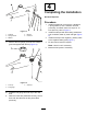
Figure13
1.Fastener4.Bracket
2.Springwasher
5.Fueltank
3.Washer
9.Removethefuel-gaugegrommetandinstallthe
grommetsuppliedwiththekit(Figure14).
g217571
Figure14
1.Fuelcap
3.Grommet
2.Fuelgauge
10.Installthefuelgaugeandfuelcaptothenew
tank.
11.Whenthehosesarepositionedcorrectly,secure
themwiththecabletiesastheyweretted
previously.
4
CompletingtheInstallation
NoPartsRequired
Procedure
1.Installthebulkheadcoverwiththe4fasteners,
4springwashers,and4washersremoved
previously,andfastenthemtoatorqueof10
N∙m(89in-lb);refertoFigure3.
2.Installthesidepodwiththeexisting3fasteners
and3washers;fastenbyhanduntiltight(Figure
2).
3.Installtheclamponthenegative(-)batterycable
tothenegativebatterypost(Figure1).
4.Fillthenewfueltankasrequired.
Note:Useafunnelifnecessary.
5.Bleedthefuelsystemifnecessary.
7