
Installation Instructions


g031627
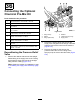
Figure216
1.Retainer
4.Rotatethepressure-relief
valve
2.Pressure-reliefvalve
5.Down
3.T-tting
4.Rotatethepressurereliefvalveupasshownin
Figure216.
Note:Alignoutletofthepressure-reliefvalve
rearward.
5.Insertthepressure-reliefvalveintothetopof
theT-ttinguntilthevalveisfullyseated(Figure
216).
6.Securethepressure-reliefvalvetotheT-tting
withtheretainerthatyouremovedinstep3.
ReplacingtheBypassHoseforthe
AgitationValve
1.Removetheretainerthatsecuresthe90°barbed
ttingforthebypasshosetotheupperT-tting
andremovethe90°ttingfromtheT-tting
(Figure217).
Note:Retaintheretainerforinstallationina
laterstep5.
g031652
Figure217
1.90°barbedtting5.UpperT-tting
2.Bypasshose
6.Gasket
3.Straightangetting
7.Flangeclamp
4.Retainer
8.Flange(agitationvalve)
2.Removetheangeclampthatsecuresthe
straightangettingandgaskettotheangeof
theagitationvalve,andremovethebypasshose
fromthemachine(Figure217).
Note:Retaintheangeclampandgasketfor
installationstep7;younolongerneedtheold
90°tting,bypasshose,andstraightange
ttingthatyouremovedfromthemachine.
3.RotatetheupperT-ttingapproximately45°
clockwise(Figure218).
98