
Installation Instructions


g292838
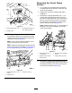
Figure82
1.Flange-headcapscrew
(3/8x1inch)
3.Flangelocknut(3/8inch)
2.Centerboomsection4.Supportbracket
5.Repeatstep4fortheothersupportbracket
(Figure82).
Note:Retaintheange-headcapscrews(3/8x1
inch)andangelocknuts(3/8inch)forinstallationin
AssemblingtheCenter-BoomSectionTrusses(page
53).Younolongerneedthecenterboomsectionand
supportbrackets.
17
AssemblingtheRearWire
HarnesstotheMachine
Partsneededforthisprocedure:
1Rearwireharness
5
Cableties
RoutingWireHarnessAlongthe
FrameTube
1.Locatethe165cm(65inches)branchandthe
203cm(80inches)branchofthenewelectrical
harness(Figure83).
g307609
Figure83
1.75.5cm(31inches)wire
harnessbranch—FLOW
METERANDAGITATION
VALVE
5.218.4cm(86inches)wire
harnessbranch—ASC10,
liftcylindersolenoids,
NOZZLE-VALVES1through
10
2.86.6cm(34inches)
wireharness
branch—SPRAY-PUMP
SOLENOID
6.30.5cm(12inches)wire
harnessbranch—speed
sensor
3.108cm(42-1/2inches)
wireharnessbranch—ring
terminalsandfuse
(unmarked)
7.127cm(50inches)wire
harnessbranch—front
harnessinterface
connectors
4.180cm(71inches)wire
harnessbranch—TO
SPRAYPUMPSWITCH
2.Routethe180cm(71inches)branch,108cm
(42-1/2inches)branch,andthe127cm(50
inches)branchofthenewelectricalharness
undertheframechannel(Figure84).
39