
Installation Instructions


g031608
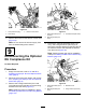
Figure36
1.Hose(eductorsupply)
3.Eductor-controlvalve
2.Hoseclamp
8.Removethehosefromtheeductor-controlvalve
(Figure36).
Note:Donotremovetheeductor-supplyhose
fromthebarbedttingattheeductor.
9
DisconnectingtheOptional
EUComplianceKit
NoPartsRequired
Procedure
1.Emptytherinsetank;referto5Aand5Bin
PreparingtheSprayerTankandOptionalRinse
Tank(page6).
2.Disconnecttherinse2tankstraps;refertostep
5CinPreparingtheSprayerTankandOptional
RinseT ank(page6).
3.Removethe2ange-headbolts(5/16x5/8
inch)thatsecuretheballvalvetothemounting
bracketfortheballvalve(Figure37).
Note:Retaintheboltsforinstallationinstep5
ofInstallingtheBallValveandMountingBracket
(page103).
g031748
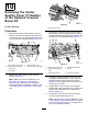
Figure37
1.Flange-headbolt(5/16x
5/8inch)
3.Threadedboss(ballvalve)
2.Mountingbracket(ball
valve)
4.Removethe2ange-headbolts(5/16x3/4
inch),and2angelocknuts(3/8inch)that
securethemountingbracketfortheballvalveto
themanifoldmount,andseparatethebracket
fromthemount(Figure38).
Note:Retaintheboltsandnutsforinstallation
instep2ofInstallingtheBallValveandMounting
Bracket(page103).
g031749
Figure38
1.Flange-headbolts(5/16x
3/4inch)
3.Manifoldmount
2.Mountingbracket(ball
valve)
4.Flangelocknut(5/16inch)
22