
Installation Instructions


1
2
3
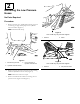
g018473
Figure15
1.Coolingassemblyinlet
port
3.Left-handpump
2.Hosefromleft-handpump
connectingtocooling
assemblyinletport
Note:Thehosefromtheright-handpumpconnectstoa
T-connector.TheshorthosecomingofftheT-connector
goestotheradiatorexitport.Theotherhoseconnectsto
thehydraulicreservoirtank
g018472
1
2
3
4
5
6
7
Figure16
1.Hydraulicreservoirtank5.Right-handpump
2.Coolingassembly
6.T-connector
3.Shorthose
7.Hoseconnectingtothe
hydraulicreservoir
4.Hosefromtheright-hand
pumpconnectingtothe
T-connector
1.Installthe61cm(24inch)hosetoleft-handpump
(Figure17.
Note:Securethehosewithahoseclampsothatthe
tabsoftheclamparepointingdownwardasshown.
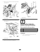
g018452
1
2
Figure17
1.Left-handpump
2.Returnport
2.Routethehoseandinstalltheotherendtothecooling
assemblyinlet.
Note:Rotatetabsonhoseclampasshownin
Figure18.
1
g018690
2
3
4
5
Figure18
1.CoolingAssemblyoutlet
4.Hosegoingtothe
T-connector
2.CoolingAssemblyInlet
5.Tabsonclamp
3.Hosecomingfromthe
left-handpump
3.InstallthehoseconnectingtheT-connectortothe
coolingassemblyoutlet(Figure16andFigure19).
7