
Installation Instructions
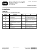


5.Alignthecoolingassemblytothereservoirbracket
(Figure12).
g018429
1
Figure12
1.Coolingassembly
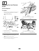
6.Usingthecorrectsetofholesforyourunit,secure
therightsideofthecoolingassemblytothehydraulic
reservoirbracketusingabolt(5/16x1inch)andnut
(5/16inch)(Figure12andFigure13).
g018428
1
Figure13
1.Boltandnut
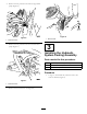
7.Usingthecoolerbracketasatemplate,drillthesecond
5/16inchholeintothereservoirbracket(Figure12,
Figure13,andFigure14).
1
g018451
Figure14
1.Boltandnut
8.Securethecoolerassemblyusingtheboltandnut
(Figure14).
4
InstallingtheLowPressure
Hoses
Partsneededforthisprocedure:
1
61cm(24inch)hose
1HoseassemblywiththeT-connector
2
Cabletie
5
Hoseclamps
Procedure
Note:Thehosefromtheleft-handpumpconnectstothe
radiatorinletport(Figure15).
6