
Installation Instructions


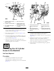


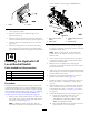


Figure19
1.PortB(hydrauliccontrol
manifold)
3.PortA(hydrauliccontrol
manifold)
2.Straighthydraulictting4.45°hydraulictting
B.Installa45°hydraulicttingintoportAof
thehydrauliccontrolmanifold(Figure19).
2.Install90°hydraulicttingsintoportsC1andC2ofthe
hydrauliccontrolmanifold(Figure20andFigure23).
Note:AlignthettingsasshowninFigure20and
Figure23.
Figure20
1.90°hydraulictting3.PortC2(hydrauliccontrol
manifold)
2.PortC1(hydrauliccontrol
manifold)
3.Install2newstraightttings(9/16x9/16x3/8inch)
intoportsC3andC4(Figure21).
Figure21
1.Femalequickdisconnect
coupling
4.Malequickdisconnect
coupling
2.Straightttings(9/16x
9/16x3/8inch—new)
5.PortC3(hydrauliccontrol
manifold)
3.PortC4(hydrauliccontrol
manifold)
4.Installthemalequickdisconnectcouplingthatyou
removedinstep3ofRemovingtheQuickDisconnect
Bracket(page10)ontothestraighthydraulicttings
(9/16x9/16x3/8inch)inportC3(Figure21).
5.Installthefemalequickdisconnectcouplingthatyou
removedinstep3ofRemovingtheQuickDisconnect
Bracket(page10)ontothestraighthydraulicttings
(9/16x9/16x3/8inch)inportC4(Figure21).
(HDX-AutoWorkmanmodels)
Note:EnsurethattheO-ringsareinstalledonthettings
andlubricatedwithhydraulicuidfromthemachinebefore
installingthettingsintothemanifold.
1.Installa45°hydraulicttingintoportBofthehydraulic
controlmanifold(Figure22).
Figure22
1.PortB(hydrauliccontrol
manifold)
3.PortA(hydrauliccontrol
manifold)
2.45°hydraulictting4.90°hydraulictting
2.Installa90°hydraulicttingintoportAofthe
hydrauliccontrolmanifold(Figure22).
3.Install90°hydraulicttingsintoportsC1andC2of
thehydrauliccontrolmanifoldasshowninFigure23.
11