
Installation Instructions


5
4
3
2
m–7176
1
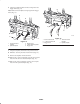
Figure 7
End view of handle
1. Latch lever
2. End of handle
3. 10 o’clock position
4. 12 o’clock position
3. Tighten the setscrew that holds the latch lever (Fig. 6).
4. Install the cable ties (Fig. 9).
5. Install the foam grip onto the bagger arm (Fig. 6).
Step
5
Installing the New Cable
Parts needed for this step:
Qty. Part
1
Cable
1 Long clevis, liquid cooled machines only
1 Short clevis
1 Clevis pin
1 Cotter pin
Procedure
1. Install the new cable to the top of the bagger with the
previously removed shoulder bolt, washer and nut
(Fig. 8).
2. Install the cable into the pulley and tighten the nut
(Fig. 8).
2
7
8
5
3
6
1
4
m–7178
Figure 8
1. Bagger arm
2. Cable
3. Shoulder bolt
4. Pulley and nut
5. Bagger door hinge
6. Cable tie
7. Nut
8. Washer
Note: Install the long cable clevis onto the bagger dump
handle if it is for a liquid cooled machine (Fig. 9).
3. Secure the bagger cable clevis to the bagger arm with
the clevis pin and cotter pin (Fig. 9).
4. Install the cable into the cable clevis installed on the
bagger handle (Fig. 9).
3
8
7
2
9
5
1
6
m–7520
5 4
Figure 9
1. Bagger dump lever
2. Bagger cable
3. Long cable clevis—liquid
cooled machines only
4. Bolt, 1/2 x 1–3/4 inch
5. Jam nut, 1/2 inch
6. Stop bracket
7. Clevis pin
8. Cotter pin
9. Stop plate
5. Adjust the handle stop, refer to Adjusting the Bagger
Arm, page 6.