
Installation Instructions


4
m–6208
84
2
5
7
3
9
1
6
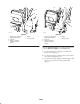
Figure 6
1. Bagger arm
2. Cable
3. Existing shoulder bolt
4. Pulley and nut
5. Bagger door hinge
6. Cable tie
7. Latch lever
8. Grip
9. ROPS (Rollover
Protection System)
Adjusting the Latch Lever
1. For a 100 Series bagger, position the latch lever
5 inches down from the top of the grip. See Figure 7.
2. For a 200 Series bagger, position the latch lever
6 inches down from the top of the grip. See Figure 7.
3. Tighten the setscrew that holds the latch lever.
4. Install the cable ties (Fig. 6).
1
m–6212
6
5
1
2
3
7
7
4
4
Figure 7
1. Bagger arm
2. Latch lever position—100
Series
3. Latch lever position—200
Series
4. Latch lever cable
5. 5 inches—100 Series
6. 6 inches—200 Series
7. Grip
Adjusting the Bagger Arm
Check the bagger arm and if needed, adjust it to remove
any slack.
1. Loosen the nuts on both sides of the stop bracket
(Fig. 8).
2. Adjust the stop bolt until there is no slack in the bagger
cable (Fig. 8).
3. Tighten the nuts on both sides of the stop bracket
(Fig. 8).