
Operator's Manual


(Figure5).Removetheconnectinglink
fromthecylinder.
B.Installtherotationalblocktothecylinder
withthepinspreviouslyremoved(Figure5).
g010840
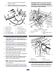
Figure5
1.Aeratorhitchpin7.Tractorlinkpin
2.Hydraulictoplink
8.Clevisandlynchpin
3.Rotationalblock
9.2-1/2foothydraulichose
4.Connectinglink10.3-1/2foothydraulichose
5.3inchextensionblock11.Hosequickcouplings
6.5inchextensionblock12.Tractorhydraulicports
2.Connectthe106cm(3-1/2foot)longhydraulic
hosetothehydraulictoplinkportwhichisclosest
totheaeratorFigure5.Applypipe-thread
sealingtapeorcompoundtothehosethreadsto
preventanyleaks.
3.Connectthe76cm(2-1/2foot)longhydraulic
hosetothehydraulictoplinkportwhichisclosest
tothetractor(Figure5).Applypipe-thread
sealingtapeorcompoundtothehosethreadsto
preventanyleaks.
4.Installquickcouplingstothehydraulichoses
(1/2-14NPTFhoseendthreadsize).Apply
pipe-threadsealingtapeorcompoundtothe
hosethreadstopreventanyleaks.
5.Connectthe2hydraulichosequickcouplingsto
theportsprovidedonthetractor.
6.Startthetractorengineandoperatethetractor
spoolvalvetochecktheextendandretract
motionofthehydraulictoplink.
Note:Reversethehoseconnections,atthe
tractor,iftheydonotagreewiththetractor
controloperation.
7.Securetherodendofhydraulictoplinktothe
mostforwardholepossibleintheaeratorbracket
withlinkpinandlynchpin(Figure6orFigure7).
Important:Whensecuringtherodendof
thehydrauliclink,usethemostforward
mountingholesinthemountingbracketso
thatthereisenoughclearanceforthebarrel
ofthecylinderwhenretracted.
g016184
Figure6
SR54andSR70mountingshown
1.Rodendofcylinder
3.Linkpin
2.Lynchpin
4.Aeratorbracket(forward
holes)
g016185
Figure7
SR72mountingshown
1.Lynchpin3.Linkpin
2.Aeratorbracket
4.Rodendofcylinder
Ifthehydrauliccylinderdoesnotreachthe
aeratormountingbracket,useanextension
blockinsteadofthestandardmountingblockto
connectthecylindertothetractor(Figure5).
9