
Operator's Manual
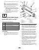


Table Of Contents
- NO TITLE
- .
- 1 Removing the Aerator from the Crating
- 2 Connecting the Lower Link Arms
- 3 Connecting the Hydraulic Top Link
- 4 Installing the Depth Gauge
- 5 Connecting the Traction Unit Upper Link
- 6 Verifying the Hydraulic Top Link Setup
- 7 Checking the PTO Angle
- 8 Fitting the PTO Shaft
- 9 Installing the PTO Shield
- 10 Connecting the PTO Shaft
- 11 Adjusting the Sway Links
- 12 Leveling the Aerator Side-to-Side
- 13 Installing the Tines
- 14 Setting the Tine Depth
- 15 Installing the Rear Guard
- 16 Removing the Storage Stands
- 17 Installing the Latch Lock
- 18 Applying the CE Decal and the Production Year Decal
- NO TITLE
- NO TITLE
- NO TITLE
- During Operation Safety
- Slope Safety
- Aerating Procedures
- Subsoil Cultivation
- Hard Ground
- Longer/Larger Tines
- Multi Row Adapter Heads
- Root Zone Lifting
- Adjusting the Tine Angle (Models SR54, SR54-S, SR70 and SR70-S)
- Adjusting the Tine Angle (Model SR72)
- Adjusting the Tine Depth (Models SR54-S and SR70-S)
- Adjusting the Tine Depth (Models SR54, SR70, and SR72)
- Adjusting the Head Return Springs
- Transport Operation
- NO TITLE
- NO TITLE
- NO TITLE
- .
- Maintenance Safety
- Lifting the Machine
- Greasing the PTO Shaft and Roller Bearings
- Gearbox Oil Specification
- Checking the Gearbox Oil
- Changing the Gearbox Oil
- Inspecting/Adjusting the Drive Chain
- Adjusting the Drive Chain
- Lubricating the Drive Chain
- Adjusting the PTO Clutch
- Fastener Torque Specifications
- Checking the Springs
- Adjusting the Hole Spacing
- Removing the Aerator from the Traction Unit
- Troubleshooting
- NO TITLE
- What is this warning?
- What is Prop 65?
- Does this law apply everywhere?
- How do the California warnings compare to federal limits?
- Why don’t all similar products carry the warning?
- Why does Toro include this warning?

10
ConnectingthePTOShaft
Partsneededforthisprocedure:
1
Pin(suppliedwiththePTOshaft)
1
Nut(suppliedwiththePTOshaft)
Procedure
Note:Youcanopentheaccesspanel(Figure22)to
easetheremovalandinstallationofthePTOshaft
mountingfasteners.
1.RemovethepinandnutfromthePTOshaft
(Figure23).
2.ConnecttheclutchendofthePTOshafttothe
aeratorgearboxinputshaftwithpinandnut
previouslyremoved(Figure23).
Note:Youcaninsertpinonlyoneway.
g010850
Figure23
1.Gearboxinputshaft
3.Pin
2.PTOshaftcoupler
4.Nut
Note:CloseandlatchthePTOshieldaccess
panelifopened.
Note:Ensurethatthepinfullyinsertsintothe
yokeofthePTO.
3.ConnectthePTOshafttothetractionunitPTO
shaft(Figure24).
g007328
Figure24
1.Tractionunitoutputshaft3.PTOshaft
2.PTOshaftcoupler
4.SlidethePTOshaftforwardasfarasthetraction
unitallows.
5.PullbackthelockingcollartosecurethePTO
shaftinplace.SlidethePTOshaftbackand
forthtoensurethatitisproperlylocked.
6.ConnecttheshieldsafetychainstothePTO
shieldandthetractionunitbracket(Figure
25).Ensurethatthechainsremainslackwhen
raisingandloweringtheaerator.
g010852
Figure25
1.Safetychains
Note:T oavoidexcesslift,connecttheliftarms
ofthetractionunitintothetopholesofthelift
bracket,ifequipped(Figure26).Themaximum
angleonthePTOshaftis35°.
16