
Operator's Manual


10
ConnectingthePTOShaft
Partsneededforthisprocedure:
1
Pin(suppliedwithPTOshaft)
1
Nut(suppliedwithPTOshaft)
Procedure
Note:Youcanopentheaccesspanel(Figure22)to
easetheremovalandinstallationofthePTOshaft
mountingfasteners.
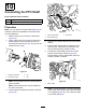
1.RemovethepinandnutfromthePTOshaft
(Figure23).
2.ConnecttheclutchendofthePTOshafttothe
aeratorgearboxinputshaftwithpinandnut
previouslyremoved(Figure23).Thepincanbe
insertedonlyoneway.
g010850
Figure23
1.Gearboxinputshaft
3.Pin
2.PTOshaftcoupler
4.Nut
Note:CloseandlatchthePTOshieldaccess
panelifopened.
Note:Ensurethatthepinisfullyinsertedinto
theyokeofthePTO.
3.ConnectthePTOshafttothetractorPTOshaft
(Figure24).
g007328
Figure24
1.Tractoroutputshaft3.PTOshaft
2.PTOshaftcoupler
4.SlidethePTOshaftforwardasfarasthetractor
allows.
5.PullbackthelockingcollartosecurethePTO
shaftinplace.SlidethePTOshaftbackand
forthtoensurethatitisproperlylocked.
6.ConnecttheshieldsafetychainstothePTO
shieldandthetractorbracket(Figure25).
Ensurethatthechainsremainslackwhenthe
aeratorisraisedorlowered.
g010852
Figure25
1.Safetychains
Note:T oavoidexcesslift,connecttheliftarms
ofthetractorintothetopholesoftheliftbracket,
ifsoequipped(Figure26).Themaximumangle
onthePTOshaftis35°.
15